Advanced Lab: Synthetic Media (IMA NYU, Spring 2024-26)
Overview
Course number: INTM-SHU 306
Course Title: Synthetic Media
Course Description:
This course investigates emerging trends in machine learning and artificial intelligence for generating media content – images, video, sound. The course explores the idea of how artists, designers, and creators can use machine learning in their own research, production, and development processes. Students will learn and understand machine-learning techniques and use them to generate creative media content. We will cover a range of different platforms and models and also experiment with implementing interaction within our work.
S1. An Introduction to Synthetic Media — General course introductions and an overview of what synthetic media is. Students are assigned readings and asked to install ComfyUI for the first time.
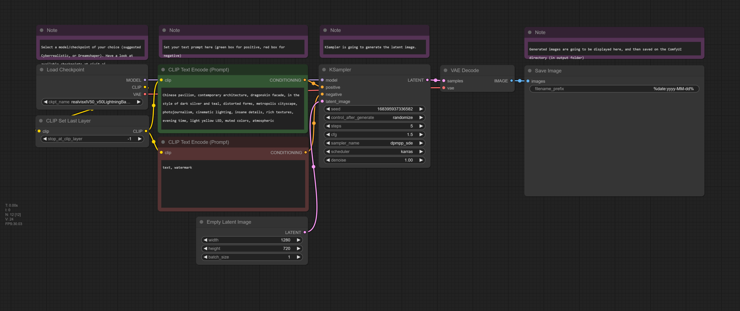
S2. Text-To-Image Generation & Prompt Engineering — Discussion of readings, with a deep dive into how text-to-image generation works, including CLIP, prompt engineering techniques, art styles/movements, and ComfyUI workflows from basic generation through upscaling. Students produce images exploring different prompts and styles.
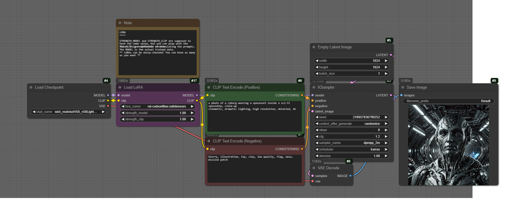
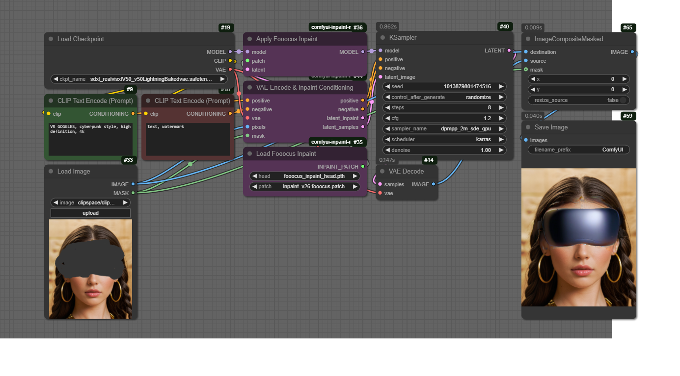
S3. Advanced Techniques for Generative AI — Builds on the basics with ControlNet, IPAdapter, LoRAs, and Inpainting — all within ComfyUI. Students learn to combine multiple techniques and begin drafting Assignment 1 (Triptych Portraits).
S4. Strategies for Project Development (Image) — Workshop-style session reviewing student drafts for Assignment 1. Class exercises cover combining LoRA + IPAdapter workflows, BLIP image interrogation, and refining image generation pipelines.
S5. Assignment 1 Presentations — Students present their Triptych Portraits. A full end-to-end ComfyUI workflow is shared, and students prepare for the video/animation sessions by installing AnimateDiff dependencies.
S6. Synthetic Video — Lecture on AI video and animation, followed by hands-on workflows: AnimateDiff text-to-video, prompt travel, and frame interpolation. Includes a RunPod cloud setup tutorial. Students create short video generations as homework.
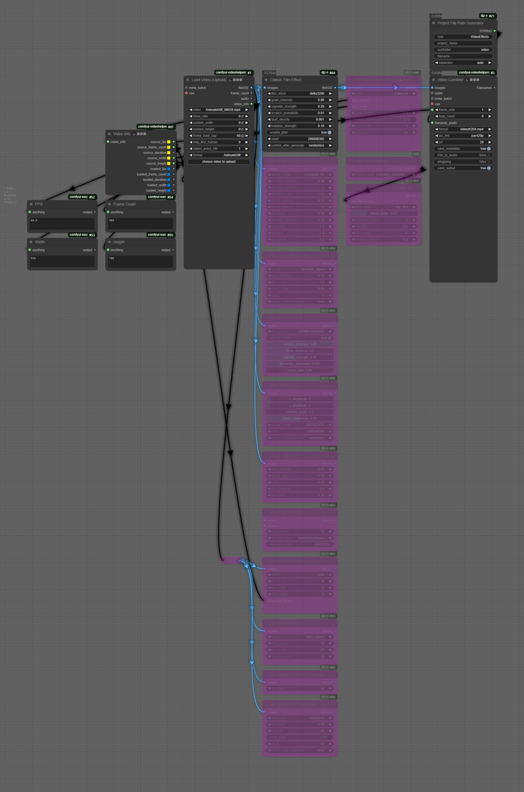
S7. Strategies for Project Development (Video) — A seminar on production workflows for AI video, plus more advanced AnimateDiff workflows including full video pipelines with upscaling and post-processing effects. Students finalize Assignment 2 (Machines & Motion).
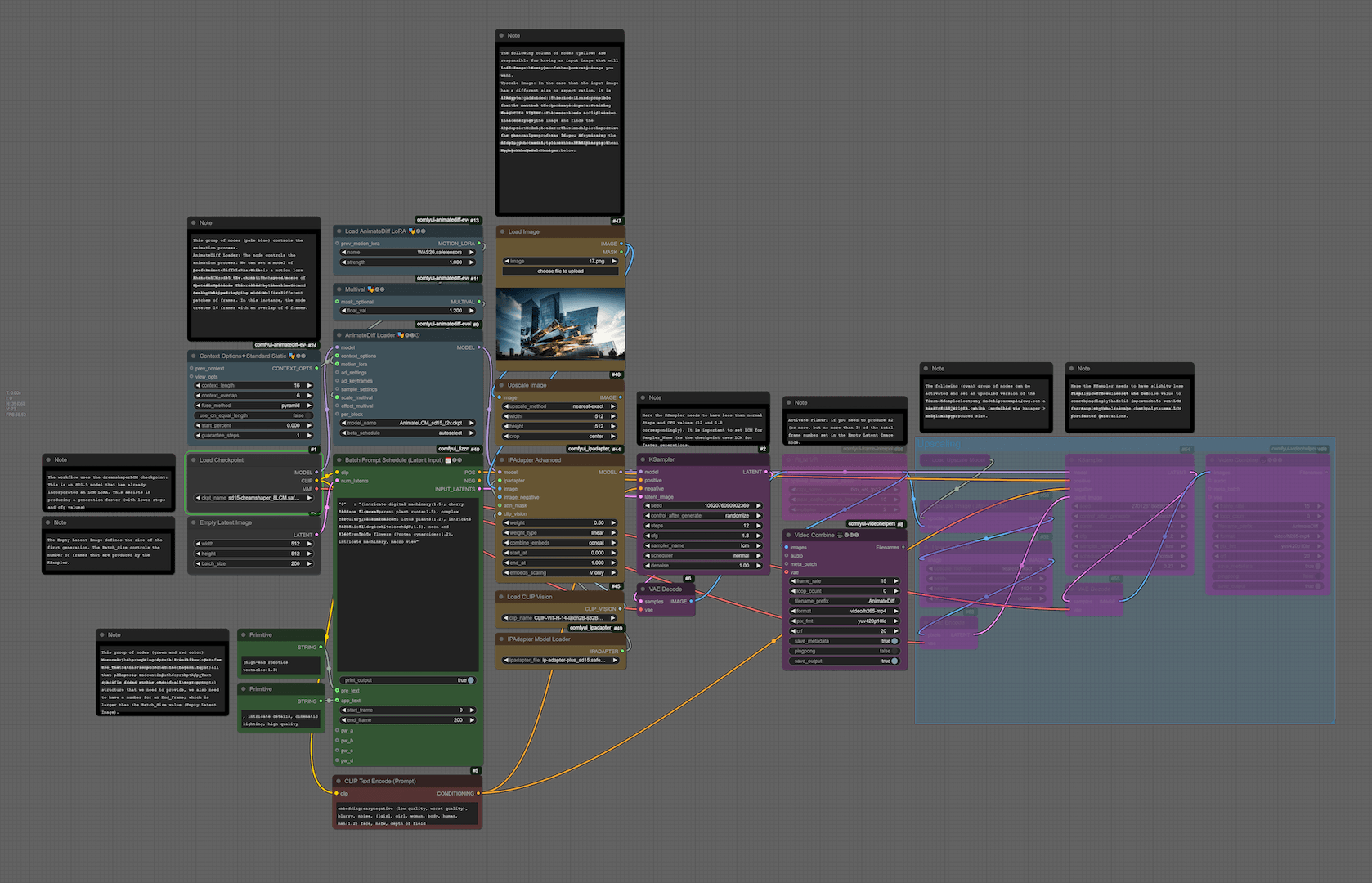
S8. Assignment 2 Tutorials & Guest Talk — ComfyCon / Shanghai Climate Week event, an advanced workflow example combining prompt travel, IPAdapter, and upscaling, plus a guest talk by Chantal Matar on AI, immersive media, and spatial design. Students begin preparing for Unity integration.
S9. Integration with Unity (Textures, Video, 3D) — Introduces Unity basics (editor, hub, primitives), then covers applying AI-generated textures and skyboxes to 3D objects, playing video on surfaces via render textures, and importing generative 3D models from LumaAI into Unity scenes.
S10. Integration with Unity (Interaction, Shaders, VFX) — Goes deeper into Unity with prefabs, C# scripting (rotation, for-loops, instantiation), Shader Graph (vertex displacement, fragment shaders, Fresnel effects), and the VFX Graph for GPU-based particle systems with turbulence, color mapping, and exposed properties.
S11. Assignment 3: Drafts & Resources — Students develop their final project (Paradigms of A(I)rt) with provided Unity project templates — image dissolve effects, portal shaders, and a virtual gallery. Resources include AI integration tools for Unity (DeepSeek, OpenAI) and artist reference examples.
Instructional Mode: In-person
Co-requisite or prerequisite: Communications Lab, What’s New Media, OR Emerging Technologies & Computational Arts
Class meeting days and times: Meets once a week, Mondays 15:45-18:30 N405
Learning Outcomes:
Upon Completion of this Course, students will be able to:
- understand the concept of synthetic media and the technologies it involves,
- learn about machine learning and generative A.I. and how to apply it creatively,
- analyze the creative and artistic dimensions of synthetic media,
- work with state-of-the-art platforms and models for generating synthetic media content,
- experiment with implementing the generated media content with platforms for interaction design,
- develop critical thinking skills through analyzing and reflecting on the implications of synthetic media in society and culture.
Course Policies
Attendance and Tardiness
Students are expected to attend all scheduled classes. If unable to attend a class, a student needs to notify their instructor before the class.
Absences and Grades
- 4 absences will lead to an F for your participation grade.
- 6 absences will lead to a 25% reduction in your final grade.
- 8 absences will lead to failure of the course.
Absence Exceptions
Observance of Religious Holidays: You may miss class for the observance of religious holidays. If you anticipate being absent because of religious observance, notify me in advance so we can create a plan for making up missed work. For more on this policy: https://www.nyu.edu/about/policies-guidelines-compliance/policies-and-guidelines/university-calendar-policy-on-religious-holidays.html
Competitions, Conferences, Presentations: You are permitted to be absent from classes to participate in competitions, conferences, and presentations, either at home or out of town, as approved by the Associate Provost for Academic Affairs. Review the Undergraduate Bulletin for the conditions you must meet to obtain approval for this kind of absence.
Extended Illness: A student with an injury or medical condition that requires ongoing accommodations (temporary or permanent) should contact the NYU Moses Center for Student Accessibility (CSA). If an accommodation is recommended by the Moses Center, then Academic Affairs may communicate on behalf of students to advocate for excused absences/ extensions. Reasonable accommodations, considering the course objectives, student learning, and fair standards, are ultimately decided by the professor.
Tardiness
Punctual arrival is mandatory for this class. Students need to be on time and not leave in the middle of class unless it is an emergency.
Late Assignments
Assignments are due at the date and time indicated on this syllabus. The late penalty for all assignments is one-third of a letter grade per day (an A becomes an A-, etc.) All other late assignments will earn an F.
Electronic Devices
Mobile Devices: Students may not use mobile devices in class unless otherwise indicated.
Recording Class: To ensure the free and open discussion of ideas, students may not record classroom lectures, discussions, and/or activities without the instructor’s advance written permission; any such recording can be used solely for their own private use. If a student has approved accommodations from the Office of Disability Resources permitting the recording of class meetings, the student must present the accommodation letter to the instructor in advance of any recording. On any days when classes will be recorded, the instructor will notify all students in advance. Distribution or sale of class recordings is prohibited without the written permission of the instructor and other students who are recorded.
Instructional Technology
Email Communication: The course instructor will contact students regularly via email. Students should check for emails from the instructor that will cover in detail reminders, logistics, updates, and so on. Please note that the instructor will try to respond to all emails within 24 hours. Students should not expect immediate responses to emails sent late at night, during holidays, or on the weekends.
Assignment Notification: All assignments will be posted on the course website. Each student is responsible for reviewing the website and its resources. After each class period, the students are asked to learn about the next homework assignment or other requirements and responsibilities related to the course.
Instructional Technology Tools and Assistance: If you need background on specific instructional technology tools, such as Zoom, NYU LMS (Brightspace) and Voicethread, check the RITS Student Toolkit. You may also email [email protected] for assistance.
Academic Honesty/Plagiarism
Carefully read NYU Shanghai’s Statement on Academic Integrity (in the Undergraduate Bulletin). Breaches of academic integrity could result in failure of an assignment, failure of the course, or other sanctions, as determined by the Academic Affairs office.
Disability Disclosure Statement
NYU Shanghai is committed to providing equal educational opportunity and participation for students with disabilities. It is NYU Shanghai’s policy that no student with a qualified disability is excluded from participating in any NYU Shanghai program or activity, denied the benefits of any NYU Shanghai program or activity, or otherwise subjected to discrimination with regard to any NYU Shanghai program or activity. Any student who needs reasonable accommodation based on a qualified disability should register with the Moses Center for Student Accessibility for assistance. Students can register online through the Moses Center and can contact the Academic Accommodations Team at [email protected] with questions or for assistance.
Title IX Statement
Title IX of the Education Amendments of 1972 (Title IX) prohibits discrimination on the basis of sex in educational programs. It protects victims of sexual or gender-based bullying and harassment and survivors of gender-based violence. Protection from discrimination on the basis of sex includes protection from being retaliated against for filing a complaint of discrimination or harassment. NYU Shanghai is committed to complying with Title IX and enforcing University policies prohibiting discrimination on the basis of sex. Mary Signor, Executive Director of the Office of Equal Opportunity, serves as the University’s Title IX Coordinator. The Title IX Coordinator is a resource for any questions or concerns about sex discrimination, sexual harassment, sexual violence, or sexual misconduct and is available to discuss your rights and judicial options. University policies define prohibited conduct, provide informal and formal procedures for filing a complaint, and a prompt and equitable resolution of complaints.
Links to the Title IX Policy and related documents:
Academic Resources
ARC Services
The Academic Resource Center (ARC) offers both individual, one-on-one tutoring as well as group sessions in a variety of ways, in a variety of courses. You can log on to WCOnline to book an appointment with a Global Writing & Speaking Fellow or a Learning Assistant (LA). The Global Writing & Speaking Fellows conduct individual consultations on writing, speaking, reading, and academic skills coaching. LAs provide both individual and small-group tutoring support in over 30 STEM, Business, Economics, IMA/IMB, and Chinese Language classes. Visit shanghai.nyu.edu/arc for more information about ARC services.
Library Services
The Library is available to support your research needs. They have access to over 27,000 print resources, 2,000 DVDs, and 1,000 databases (including over a million ebooks, as well as streaming audio and video and image databases).
Librarians with expertise in your research topic are available to meet either in person or online by appointment or by email to help you navigate the research process. Our library team features experts in Business, Arts & Humanities, STEM, Social Sciences & Economics, and data tools & resources. Ask us how we can assist you in developing a research question and formulating a research strategy, selecting databases, requesting materials, and citing your sources. Visit shanghai.nyu.edu/library for more information on:
- 24/7 access to e-books, e-journals, streaming media, and databases
- Booking one-on-one consultations for research help
- Asking the Library questions via chat or email
Electronic Reserves
Students can access course readings using their NYU credentials for courses they currently enrolled in at https://ares.library.nyu.edu/.
Interlibrary Loan Service
For materials not available to you immediately, you can request scanned copies of a book chapter or journal article through our Interlibrary Loan (ILL) service. If you don’t know which chapter you need, you can request a Table of Content through ILL.
Assignments & Grading
For all assignments, you are required to demonstrate three important skills:
- Divergence: A need to showcase thorough research, investigation, and experimentation. It is often impossible to reach superb results if the initial research is limited and lacks depth and quality of resources or information.
- Criticality: It is paramount to be able to critically reflect on the researched or practiced content and identify what to keep and what to ignore. This skill can be sharpened if you are exposed frequently and to a sufficient amount of content from other artists and practitioners and understand in more detail their methods and motivations.
- Convergence: After you have done a wide series of experiments and you have critically reflected on the content, you need to showcase your convergence skills. In this stage, it is essential to focus on the optimization and exceptional refinement of your content. Rough outputs that lack numerous reiterations show poor results, even if the previous stages are completed perfectly. Consider planning ahead of time for making the necessary refinements that will showcase incredible final results.
Class Participation & Attendance
Active participation and attendance are essential in this course. Students will be required to proceed to various teaching and learning activities during class, such as discussions, debates, practical exercises, and more.
Homework & Reading Responses
The course necessitates the completion of homework such as readings, writings, and practical exercises. These are important elements that are required for achieving the learning outcomes of this course.
Marking Elements
| Class Participation & Attendance | 20% |
|---|---|
| Homework & Reading Responses | 15% |
| Assignment 1 | 15% |
| Assignment 2 | 20% |
| Assignment 3 | 30% |
Letter Grades
| Letter Grade | Percentage |
|---|---|
| A | 95% – 100% |
| A- | 90% – 94.99% |
| B+ | 87% – 89.99% |
| B | 83% – 86.99 |
| B- | 80% – 82.99% |
| C+ | 77% – 79.99% |
| C | 73% – 76.99% |
| C- | 70% – 72.99% |
| D+ | 67% – 69.99% |
| D | 63% – 66.99% |
| F | 63% and lower |
Assignment 1 – Triptych Portraits
(medium: generative image | work individually)
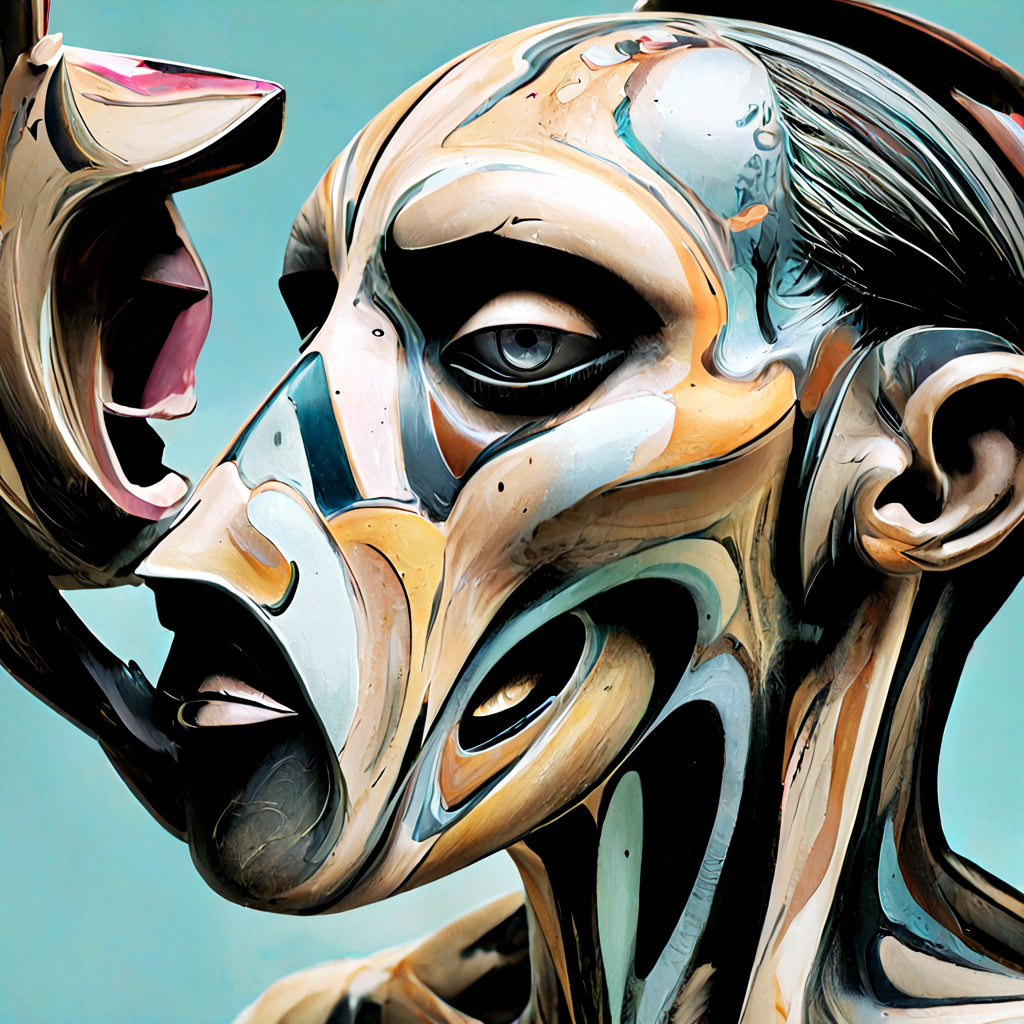
Prompt: Create a triptych of the real YOU (your “portrait”). This assignment is inspired by the triptychs of Francis Bacon. The artist used the format to split a single subject so as to convey a visual metaphor for the multifaceted and sometimes fragmented nature of his own identity and capture layers of states of being such as internal conflicts, vulnerability, and the passage of time. He utilized distorted, almost dismembered forms to suggest a struggle with inner demons and existential anxiety. Via his signature unsettling, raw imagery, he manages to convey a fascination of the flesh, depicting a candid exploration of human emotions, the inevitability of decay, mortality, and redemption.
You are free to interpret the prompt in a way that makes sense to you; consider viewing this with honesty, courage, and depth. This is not a psychological profiling but rather a snapshot of the holistic perception of who you are.
Technically speaking, you need to provide the triptych in a printed format (~A3 size), and to submit a folder with the final images (.png or .jpeg format, 2K/4K resolution). The images need to contain the workflow (or you can submit the workflow as additional files in JSON format). Your workflows need to have (a) a two-pass sampling system (b) a ControlNet implementation, (c) an IPAdapter with multiple images, and (d) at least one LoRA. You may optionally use Midas for depth estimation or an Inpainting sequence.
(add a folder as: SurnameName)
S1. An Introduction to Synthetic Media
- General Introductions & Course Overview
- An Introduction to Synthetic Media
Homework (deadline: Mon 10 Feb, by 3pm)
- Readings:
- AI2041 Ten Visions of the Future (read at least one chapter from the following list)
We are going to discuss the reading in the next session.
- Practice:
- Install ComfyUI (version:
ComfyUI_windows_portable)
- Windows (free, needs NVIDIA )
- Mac (free, needs M1 or above)
- Cloud Servic es (paid, resources included)
- Install ComfyUI (version:
- Readings:
 https://www.comfy.org/download
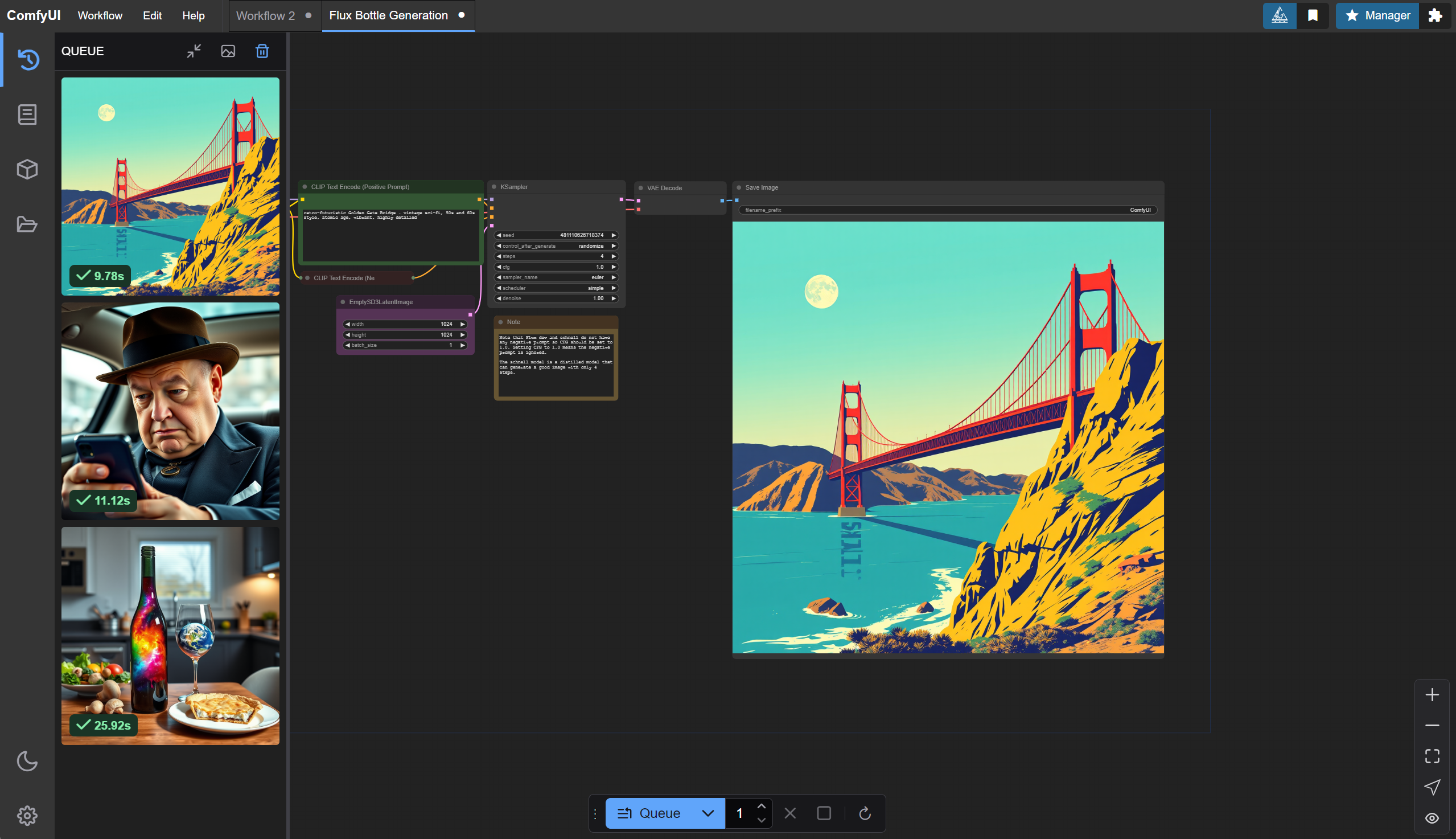
 https://github.com/comfyanonymous/ComfyUI?tab=readme-ov-file#installing
 https://stable-diffusion-art.com/how-to-install-comfyui/
 https://shadow.tech/shadowpro/offers
.png)
S2. Text-To-Image Generation & Prompt Engineering
- Readings Discussion
Text-To-Image Generation & Prompt Engineering
ComfyUI Installation Instructions
https://github.com/comfyanonymous/ComfyUIhttps://github.com/ltdrdata/ComfyUI-ManagerOnline Access:
Workflows
- Text to Image (basic)
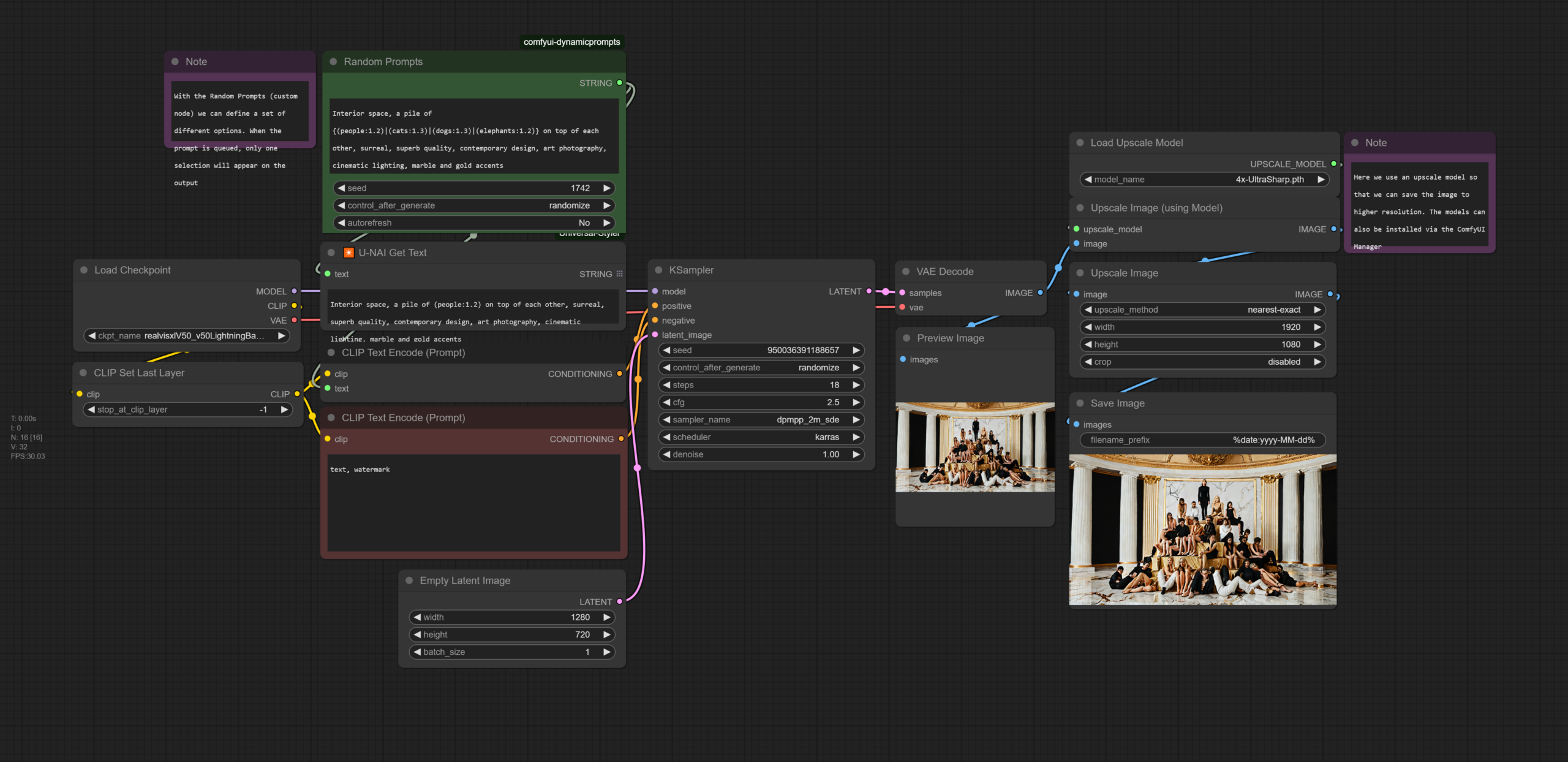
- Text to Image (random prompts)
- Text to Image (upscaling)
- Text to Image (second pass upscaling
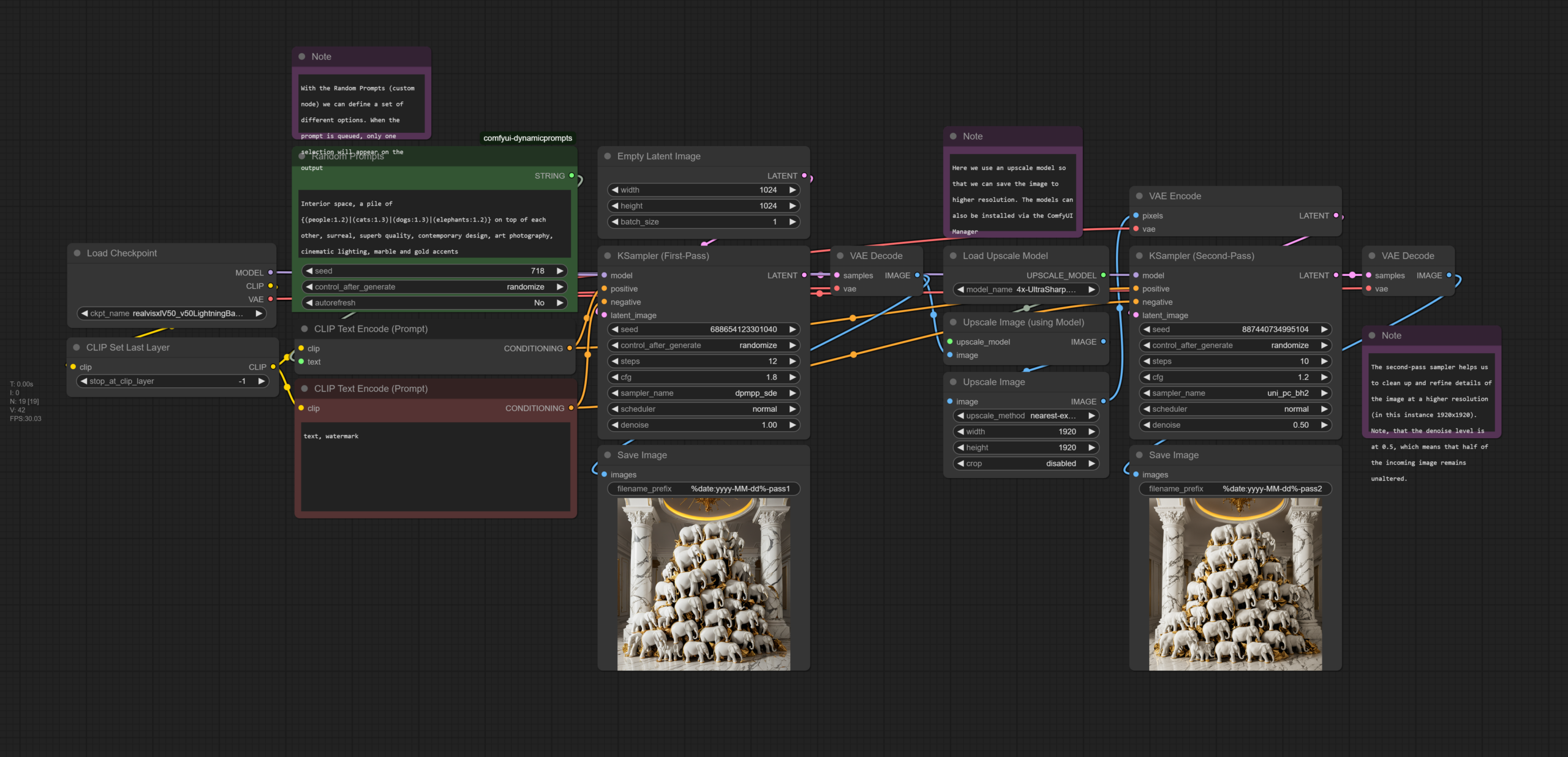
- Text to Image (upscaling)
- Text to Image (basic)
Text-To-Image / Prompt Engineering
Understanding Styles/Movements/Techniques
Communities/Repositories/Models/Workflows
Online Tutorials/Documentation
 https://blenderneko.github.io/ComfyUI-docs/
 https://midlibrary.io/categories/techniques


 https://www.youtube.com/watch?v=LNOlk8oz1nY

Homework (deadline: Mon 17 Feb, by 12 noon)
- Reference: How Does Image Generation Work?
- Reading: Margaret Boden – The Creative Mind (In a Nutshell). We are going to discuss the reading in the next session.
- Practice: Develop 20 high-resolution images that each explore a different prompt engineering, and/or different art styles, and/or different input images. Make sure that the images contain the ComfyUI workflow as well (so that we can see both the image and the workflow).
Upload Final Images Here: Submission Folder (SurnameName-1.png, etc)
S3. Advanced Techniques for GenerativeAI
- Readings Discussions
Advanced Techniques for Image Generation
Reference Slides on Art Methdologies
Workflows
Suggested ComfyUI nodes: Crystools (custom_nodes)
Download Models:
- 通过网盘分享的文件:ComfyUI-Models
链接: https://pan.baidu.com/s/1ni4ASaL_HDeAlE_xQVQ1DQ?pwd=gk2r 提取码: gk2r
- Drive: (1) models/controlnet (2) models/ipadapter, models/clipvision (3) models/loras (4) models/inpaint
1. ControlNet
- Install T2I-adapter-SDXL.fp16.safetensors model via ComfyUI Manager or download model via links above.
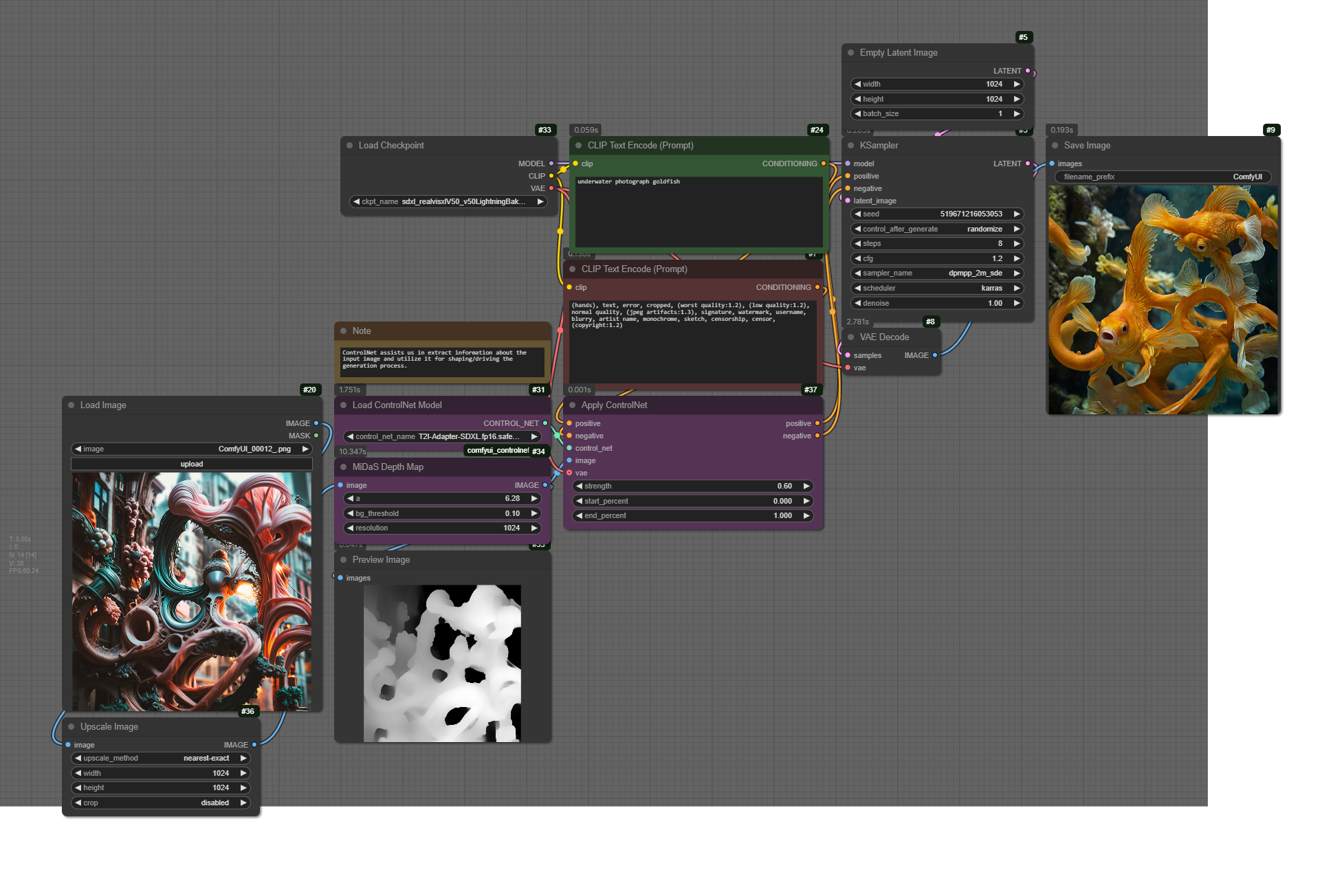
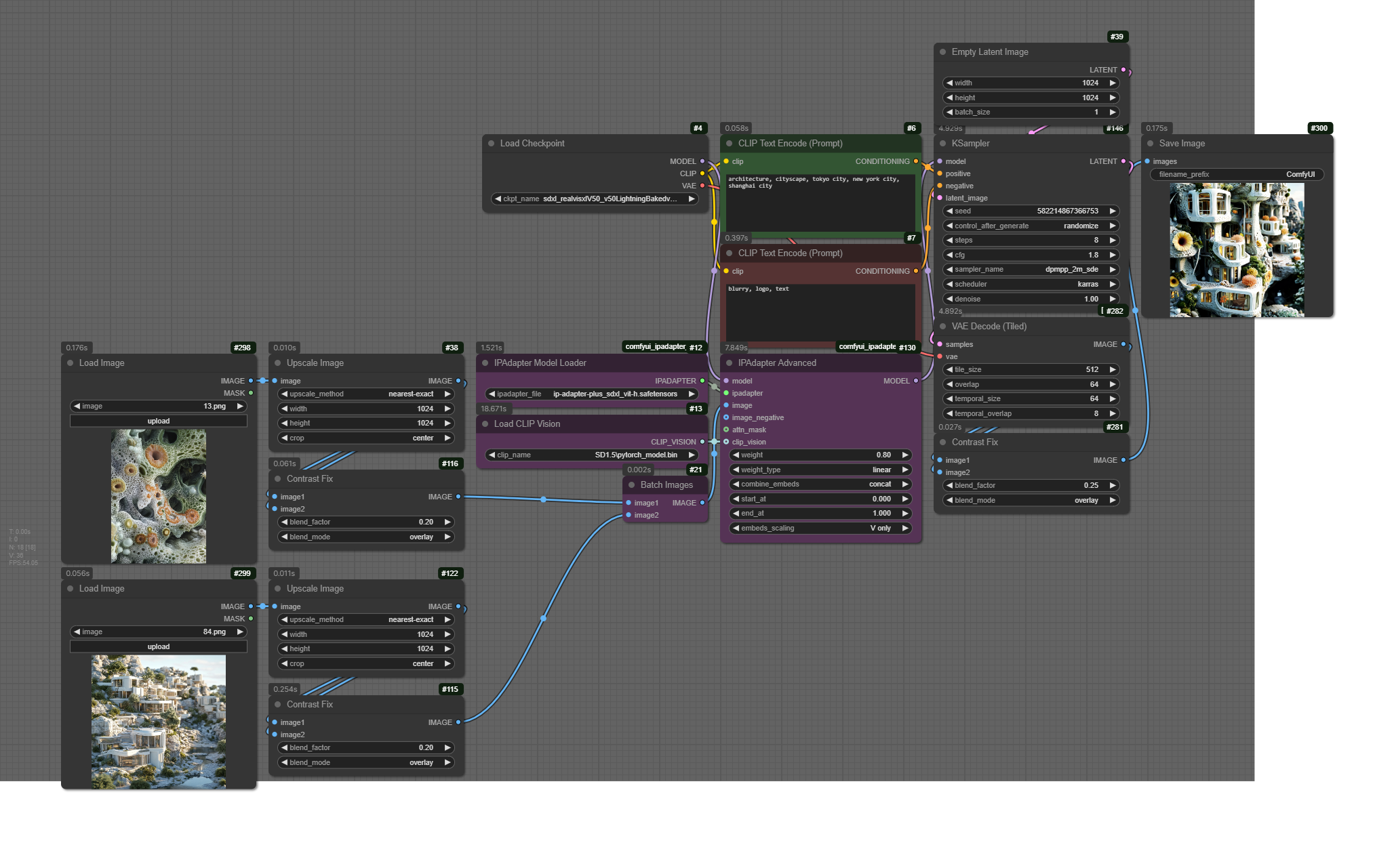
- IPAdapter
- ComfyUI IPAdapter Nodes (custom_nodes)
- IPAdapter Model: ip-adapter-plus_sdxl_vit-h.safetensors (models/ipadapter)
- ClipVision Model: download model pytorch_model.bin or via links above, and put in ./models/clip_vision/SD1.5/pytorch_model.bin)
- LoRA
- Find LoRAs on CivitAI (models → filter: LoRA, SDXL)
- Drive link (example lora files)
- Inpainting
- ComfyUI Inpaint Nodes (via GitHub or ComfyUI Manager)
- 通过网盘分享的文件:ComfyUI-Models
- Homework (next week): First Draft/Iteration for Assignment 1
S4. Strategies for Project Development (Image)
- Assignment Drafts (Review & Discussion)
Workflows – Class Exercises
- Class Example (fixed/random & weightings) – image with embedded workflow
- Lora+IPAdapter Example
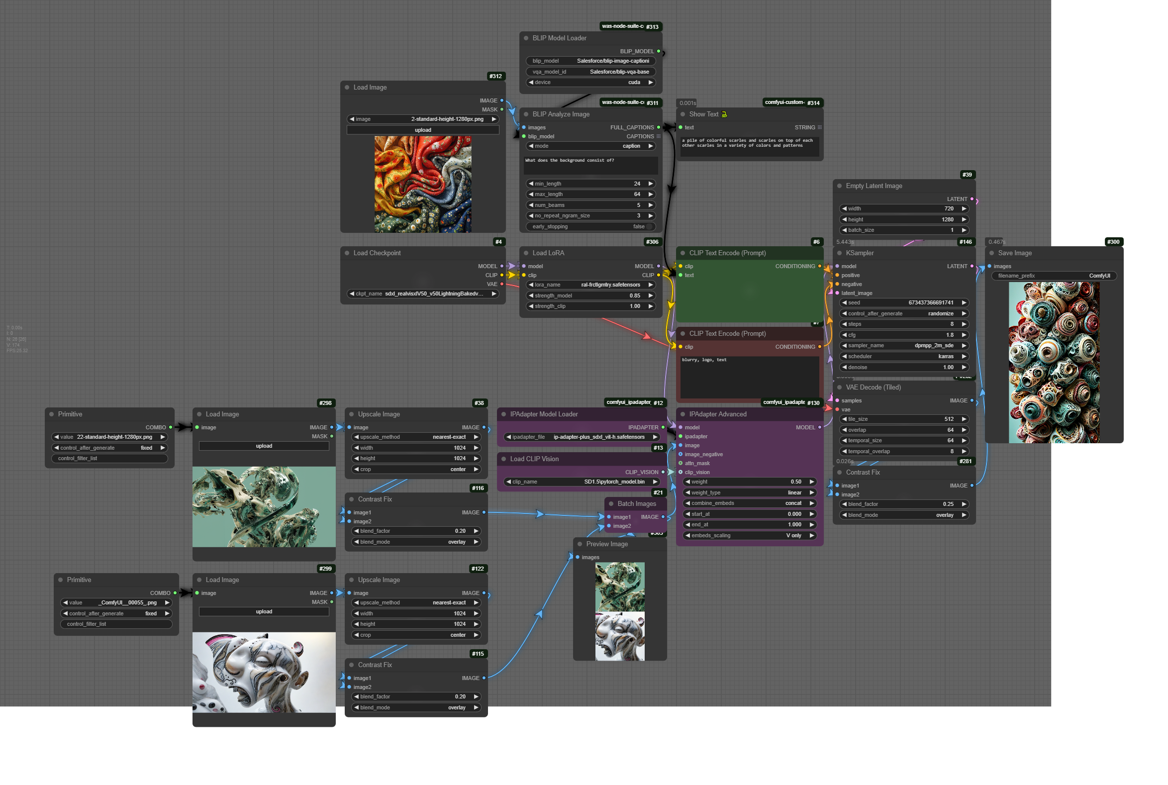
- Blip – Image Interrogation
- Suggested Nodeshttps://github.com/AEmotionStudio/ComfyUI-EnhancedLinksandNodes
- Tutorials
S5. Assignment 1 Presentations
- Assignment 1 Presentations
- Full Workflow

S6 Preparation: Install dependencies for Video/Animation sessions
- models/checkpoint: https://civitai.com/models/4384/dreamshaper
- models/loras: SD1.5/lcm/pytorch_lora_weights.safetensors
- models/animatediff_models: v3_sd15_mm.ckpt
Assignment 2 – Machines & Motion
(medium: generative video & sound | work individually OR groups of two)
Prompt: In this assignment, you are asked to create a 1 to 2-minute video that explores motion in computational systems, machine hallucinations, or unconscious states of A.I. Unlike traditional animation, movement here is not just about objects shifting in space but about patterns emerging, structures unfolding, and logic evolving over time. How does an algorithm expresses and understands motion? How does data transform when set into motion? Your video should capture motion as a generative process – whether through fluid transitions, recursive loops, glitch disruptions, or emergent formations.
In terms of technical details, you need to submit a final video and a folder with your project files. The video must be in .mp4 format (1920×1080 or higher 4K), between 1 to 2 minutes, and include a workflow file documenting the processes used. Your workflows must incorporate: (a) a generative motion process (b) a structured sound layer, which could be generative music, algorithmic soundscapes, or fragmented digital textures, (c) (optional) a text or narration component, which may be an AI-generated script, a poetic reflection, or a conceptual statement.
Upload the final content HERE (add a folder as: SurnameName)
S6. Synthetic Video
Workflows
- S6-1 – Workshop File (base)
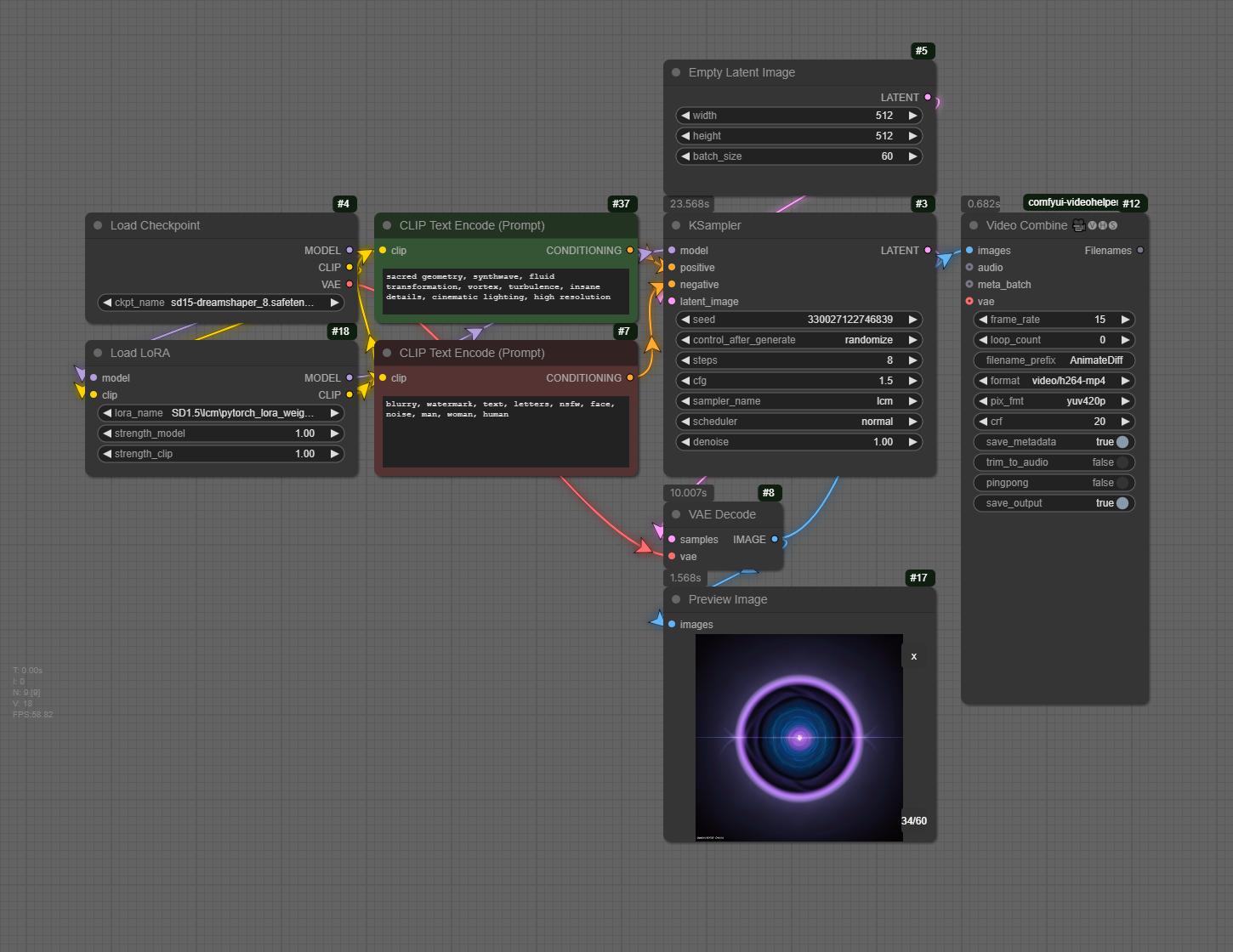
- S6-2 – AnimateDiff Text-To-Video
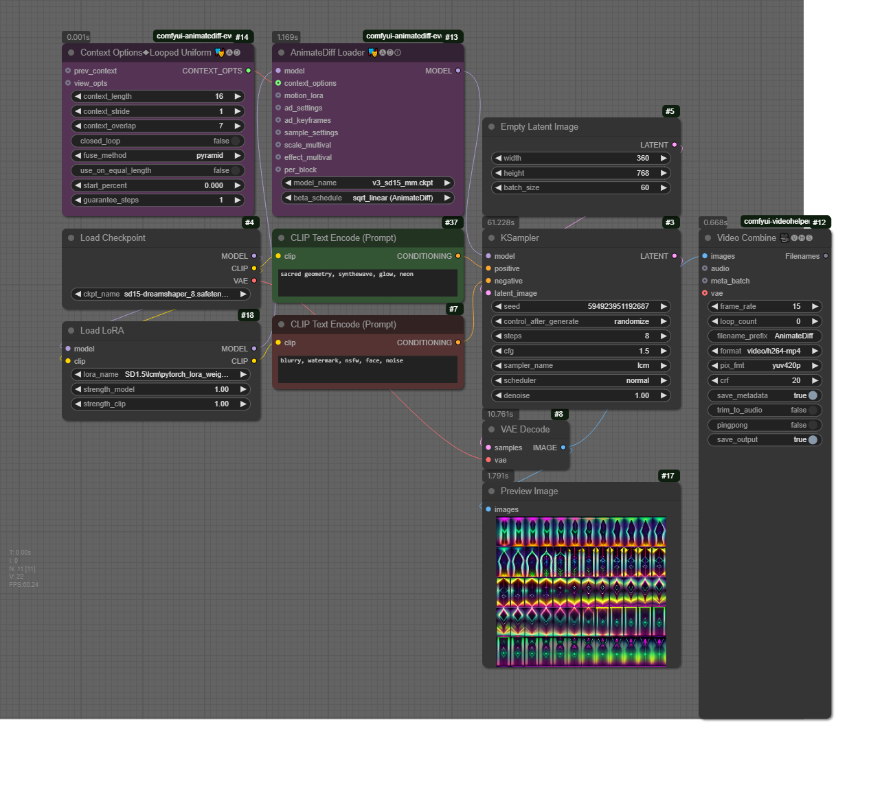
- S6-3 – AnimateDiff Prompt Travel
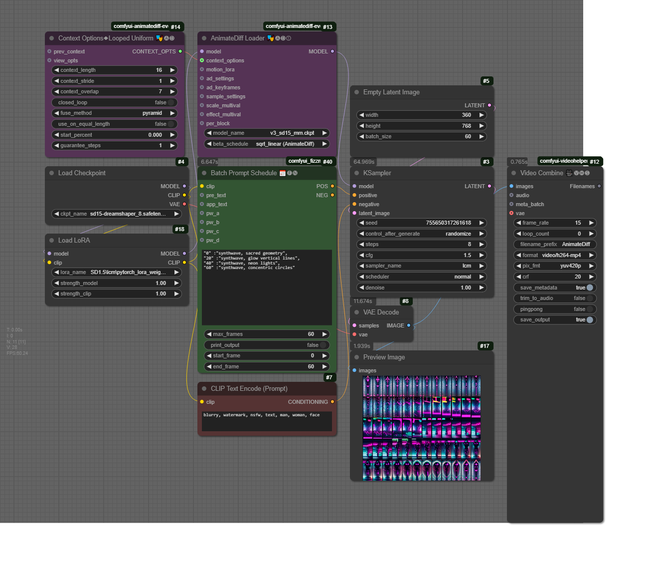
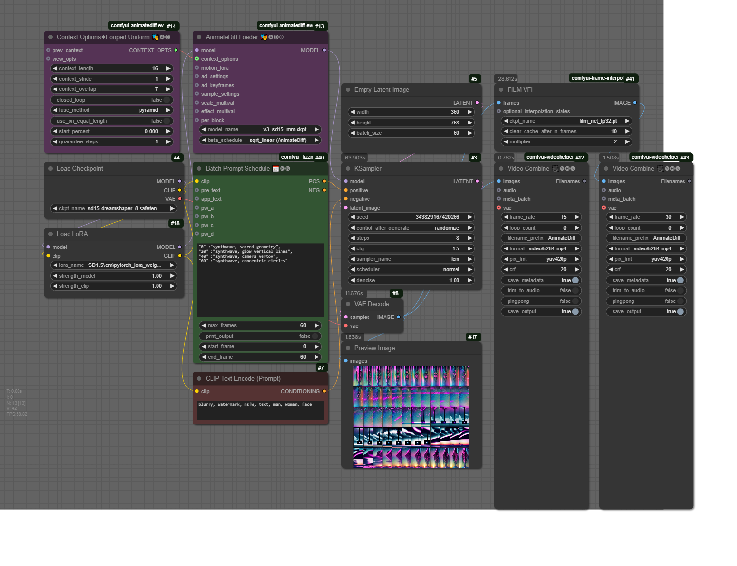
- S6-4 Frame Interpolation

RunPod Tutorial (Cloud Service)
In RunPod, you can set up your custom machine learning, generative AI, or ComfyUI projects. Below are the commands used in this tutorial (for easier copy-pasting during setup).
1️⃣ Set Up Storage Space
- Allocate 100GB of storage before creating the pod.
2️⃣ Create a New Pod
- Attach Storage: When deploying a pod, add your storage space (this option appears at the top of the Deploy GPU Pod page).
- Select a GPU: A GPU costing around $0.5/hour (with at least 20GB VRAM) should be sufficient for generative video tasks.
- Choose a Template:
- Select RunPod Pytorch 2.1.
- Click Edit Template, then under Expose HTTP Ports, add:
8888,8188
3️⃣ Set Up the Environment
Once the pod is set up and ready, go to Connect → Jupyter Lab and follow these steps:
- Open a Terminal and install PyTorch:
pip install --pre torch torchvision torchaudio --index-url https://download.pytorch.org/whl/nightly/xpu
- Clone ComfyUI Repository:
git clone https://github.com/comfyanonymous/ComfyUI.git
- Install ComfyUI Requirements:
cd ComfyUI/
pip install -r requirements.txt
- Install ComfyUI Manager:
cd custom_nodes/
git clone https://github.com/ltdrdata/ComfyUI-Manager.git
cd ComfyUI-Manager
pip install -r requirements.txt
cd ../..
- Download a Model Checkpoint:
cd models/checkpoints/
wget -O dreamshaper8LCM.safetensors "https://civitai.com/api/download/models/252914?type=Model&format=SafeTensor&size=pruned&fp=fp16"
cd ../..
- Run ComfyUI:
python3 main.py --listen
4️⃣ Access ComfyUI
- Go back to your pod, click Connect, then select HTTP Service.
- ComfyUI should open in a new browser window.
Homework
- Reading (mandatory): https://drive.google.com/file/d/195Cp_iDcgWwGf2g__wFh_UydnSmQM_QY/view
- Practice: Create 3 video generations: one with text-to-video, one with prompt travel, and one with image-to-video.
- Each video needs to have different prompts and/or input images (when applicable)
- Each video duration: 5 seconds
- Size: 768:512 or 512:768
- Add your videos here (inside a folder with NameSurname)
S7. Strategies for Project Development (Video)
Workflows
- S7 – Text2Video
❗Important: Make sure that you use the following two models:
- dreamshaper_8LCM.safetensors (CivitAI): place the model inside /models/checkpoints
- AnimateLCM_sd15_t2v.ckpt (HuggingFace): place the model inside /models/animatediff_models
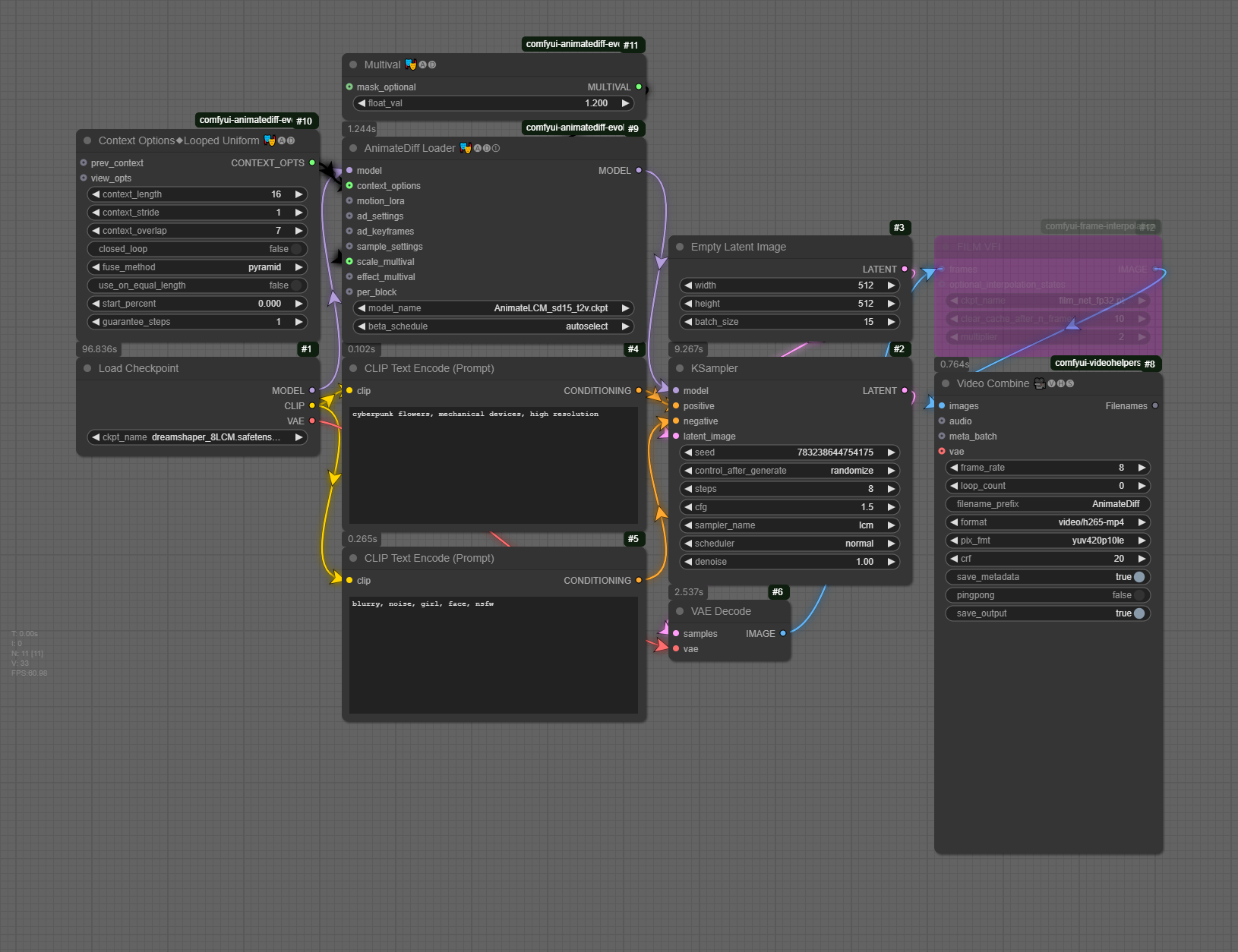
- S7 – VideoFull
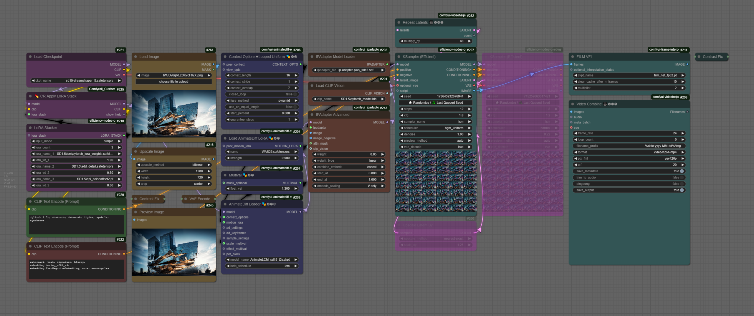
- S7-1 PostProcessing Video
- S7 – Text2Video
S8. Assignment 2 Tutorials & Guest Talk
ComfyCon | Shanghai Climate Week
Guest Talk (5.30-6.30PM, @N306)
Guest Talk by Chantal Matar: AI, Immersive Media & Spatial Design
Chantal Matar is a multidisciplinary Lebanese-British architectural and generative designer specializing in the intersection of mixed media and architecture. Her work is deeply influenced by art, nature, and emerging technologies, particularly Artificial Intelligence, which she integrates into her research, digital aesthetics, and built environments. She has led workshops and delivered lectures at some of the world’s leading institutions and conferences, including MIT, EPFL, and UCL Bartlett. Her work has been showcased internationally, including the Venice Biennale and at multiple galleries and exhibitions around the world.
Homework (7 April)
- Viewing: Corpora as Medium
Installation: Unity Engine & Review of Basics
To start developing a project with Unity, you first need to install it in our system:
- Unity Hub and an LTS Unity Editor (recommended: 6000.0.xx)
Following the installation of the required software, you can open the Unity Hub, which is a tool that allows you to manage your Unity projects as well as manage and install different versions of Unity in one centralized location.
Unity Hub
When you open Unity Hub for the first time, you will be prompted to log in with your Unity ID. If you don’t have one, you can create it for free. In Unity Hub’s Preferences menu, select License, and activate a Personal license (which is free). The personal licenses expire after a few days, but you can install it again with the same process.
The Unity Hub will show you a list of all Unity versions installed on your computer (you can have multiple versions of Unity if you want). If you don’t have any versions installed, you can click on the “Installs” button to install a new version.
Here are the main tabs that you need to know about Unity Hub:
- Projects – To open an existing project or create a new one, click on the “Projects” button and then select the option that you want.
- Installs – To manage and install different versions of Unity, click on the “Installs” button. Here you can see all the versions of Unity installed on your computer, and you can also install new versions or delete old ones.
- Learn – To access Unity documentation and tutorials, click on the “Learn” button.
- Other options include the Community, UOS, and Developer Services (which are not going to be covered).
Creating a Project with the Unity Hub
To create a new project in Unity, open the Unity Hub and click on the “New Project” button. In the “New Project” window, select the appropriate version for your project from the drop-down menu – 6000.0.xx. Next, select the URP (Universal Rendering Pipeline) or the HDRP (High Definition Rendering Pipeline) template from the list of templates.
In the right side panel, set the project name and location. You can also choose to create a new folder for your project if you want to. Finally, uncheck the checkbox for “Enable PlasticSCM”. This will prevent Unity from using the PlasticSCM version control system for your project.
Click on the “Create Project” button to create your new Unity 3D project. Once the project is created, you will be taken to the Unity editor where you can start working on your application.
Unity Editor
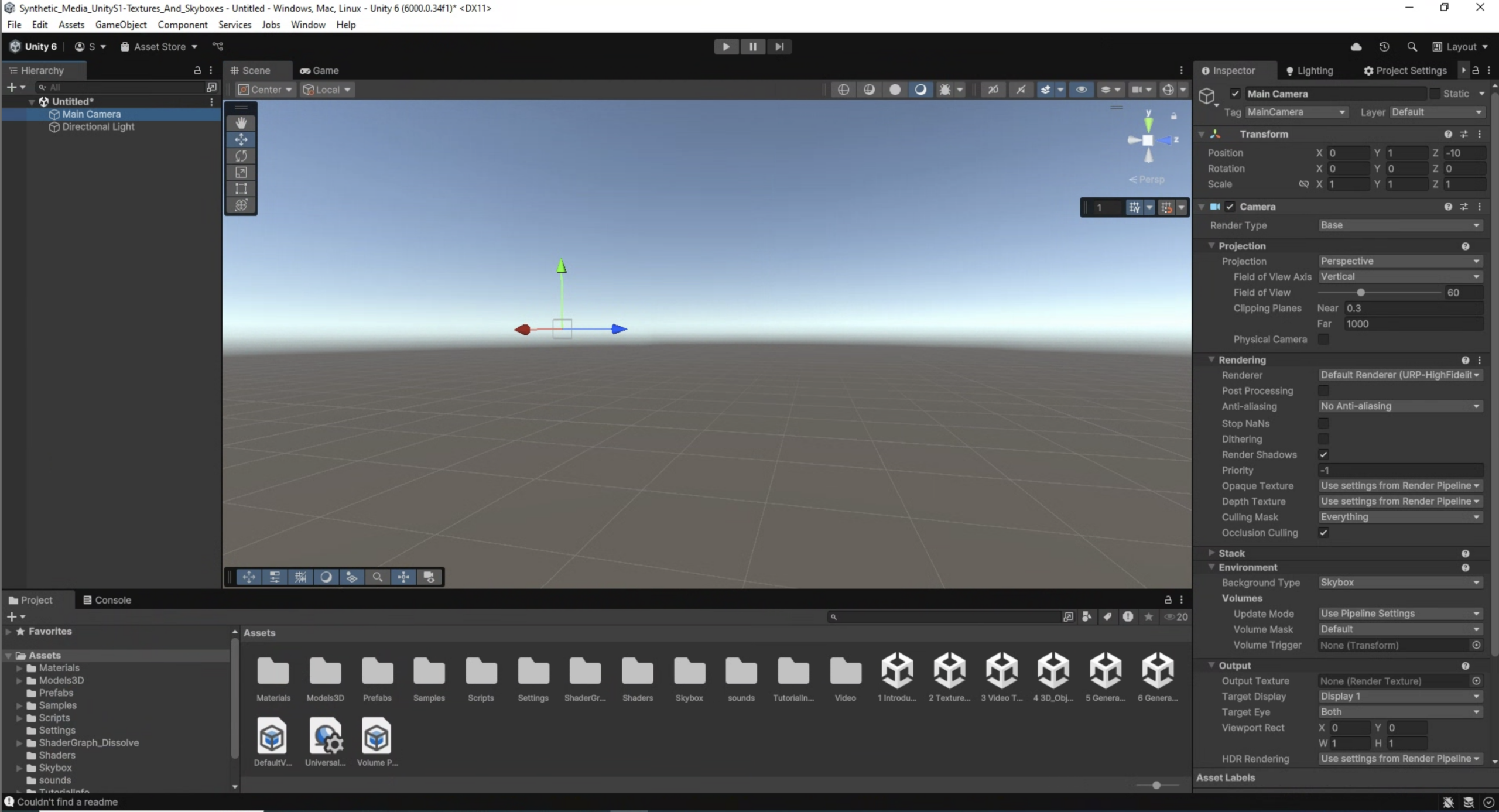
The Unity editor is divided into several main areas. The most important ones are the following: the Scene view, the Game view, the Hierarchy, the Project, Inspector, and Console.
- The Scene view is where you can see and edit your 3D objects in your scene. You can navigate and manipulate the camera, as well as select and move objects in the Scene view.
- The Game view is where you can see what your game or application will look like when it is running. You can run the “Game” by clicking on the Play/Stop buttons at the top of the screen.
- The Hierarchy is where you can see all the objects in your scene organized in a hierarchical tree structure. You can select, move, and delete objects from the Hierarchy.
- The Project is where you can access all the assets and files in your project. You can import new assets, create new folders, and access the scripts and prefabs in your project.
- The Inspector is where you can see and edit the properties of the currently selected object. You can change the object’s position, rotation, scale, as well as access its materials, scripts, and other components.
- The Console is where we can check if everything runs correctly with our project. This helps us to debug code or other issues that may occur during execution.
Other important panels and features include the Toolbar, Lighting, and more.
- The Toolbar at the top of the Unity editor is where you can access different tools such as the move, rotate, and scale tools. You can also access different windows and settings from the Toolbar.
- The Hand Tool allows panning around the Scene.
- Press key Alt (Windows) or Option (Mac) and left-click and drag to Orbit the Camera around the current pivot point.
- Scroll (mouse or keypad) to zoom in and out the scene.
- The Move, Rotate, Scale, Rect Transform and Transform tools allow you to edit individual GameObjects.
- Shortcuts: Q-W-E-R-T-Y
- The Lighting window is where you can set up and adjust lighting for your project. You can add and adjust lights, as well as change the environment settings.
- Additional windows and panels can be found on the main Unity Menu/Windows.
Primitives
To add 3D objects in the scene go to the Hierarchy panel, and either click the + sign, or right click on the Hierarchy panel area, to have the sub-menu appear. Select 3D Object, then choose the type of object you want to create, such as a cube, sphere, or plane. The new object will appear in the Hierarchy panel and the Scene view.
You can move, rotate and scale the object in the Scene view (by using the Unity’s Transform component), as well as from the number boxes that appear in the Inspector panel.
Each GameObject can be configured from the Inspector window. Properties such as position, rotation, size are set here. If the GameObject includes materials or additional properties, they can all be accessed from here as well.
Assignment 3 – Paradigms of A(I)rt
(medium: agnostic | work individually OR groups of two/three)
- Prompt: For the final project, you are given more freedom to explore a topic of your own choosing related to synthetic media. You may choose to create a new generative model using machine learning techniques, implement a creative application of synthetic media for a specific purpose or design an interactive experience that showcases the potential of synthetic media in a philosophical, sociopolitical or artistic context. Moreover, you are encouraged to incorporate the concepts and techniques covered throughout the course and should be expected to produce a significant output, such as an immersive experience, an interactive installation, or an audiovisual composition. The final project is expected to be presented in a public showcase/exhibition, allowing all of you to share their work with broader audiences.
 https://mp.weixin.qq.com/s/br974nBQr-UeOGvkQBq1-w
S9. Intergration with Unity (textures, video, 3D)
Unity Basics
To start developing a project with Unity, you first need to install it in our system:
- Unity Hub and an LTS Unity Editor (recommended: 6000.0.xx)
Following the installation of the required software, you can open the Unity Hub, which is a tool that allows you to manage your Unity projects as well as manage and install different versions of Unity in one centralized location.
Unity Hub
When you open Unity Hub for the first time, you will be prompted to log in with your Unity ID. If you don’t have one, you can create it for free. In Unity Hub’s Preferences menu, select License, and activate a Personal license (which is free). The personal licenses expire after a few days, but you can install it again with the same process.
The Unity Hub will show you a list of all Unity versions installed on your computer (you can have multiple versions of Unity if you want). If you don’t have any versions installed, you can click on the “Installs” button to install a new version.
Here are the main tabs that you need to know about Unity Hub:
- Projects – To open an existing project or create a new one, click on the “Projects” button and then select the option that you want.
- Installs – To manage and install different versions of Unity, click on the “Installs” button. Here you can see all the versions of Unity installed on your computer, and you can also install new versions or delete old ones.
- Learn – To access Unity documentation and tutorials, click on the “Learn” button.
- Other options include the Community, UOS, and Developer Services (which are not going to be covered).
Creating a Project with the Unity Hub
To create a new project in Unity, open the Unity Hub and click on the “New Project” button. In the “New Project” window, select the appropriate version for your project from the drop-down menu – 6000.0.xx. Next, select the URP (Universal Rendering Pipeline) or the HDRP (High Definition Rendering Pipeline) template from the list of templates.
In the right side panel, set the project name and location. You can also choose to create a new folder for your project if you want to. Finally, uncheck the checkbox for “Enable PlasticSCM”. This will prevent Unity from using the PlasticSCM version control system for your project.
Click on the “Create Project” button to create your new Unity 3D project. Once the project is created, you will be taken to the Unity editor where you can start working on your application.
Unity Editor
The Unity editor is divided into several main areas. The most important ones are the following: the Scene view, the Game view, the Hierarchy, the Project, Inspector, and Console.
- The Scene view is where you can see and edit your 3D objects in your scene. You can navigate and manipulate the camera, as well as select and move objects in the Scene view.
- The Game view is where you can see what your game or application will look like when it is running. You can run the “Game” by clicking on the Play/Stop buttons at the top of the screen.
- The Hierarchy is where you can see all the objects in your scene organized in a hierarchical tree structure. You can select, move, and delete objects from the Hierarchy.
- The Project is where you can access all the assets and files in your project. You can import new assets, create new folders, and access the scripts and prefabs in your project.
- The Inspector is where you can see and edit the properties of the currently selected object. You can change the object’s position, rotation, scale, as well as access its materials, scripts, and other components.
- The Console is where we can check if everything runs correctly with our project. This helps us to debug code or other issues that may occur during execution.
Other important panels and features include the Toolbar, Lighting, and more.
- The Toolbar at the top of the Unity editor is where you can access different tools such as the move, rotate, and scale tools. You can also access different windows and settings from the Toolbar.
- The Hand Tool allows panning around the Scene.
- Press key Alt (Windows) or Option (Mac) and left-click and drag to Orbit the Camera around the current pivot point.
- Scroll (mouse or keypad) to zoom in and out the scene.
- The Move, Rotate, Scale, Rect Transform and Transform tools allow you to edit individual GameObjects.
- Shortcuts: Q-W-E-R-T-Y
- The Lighting window is where you can set up and adjust lighting for your project. You can add and adjust lights, as well as change the environment settings.
- Additional windows and panels can be found on the main Unity Menu/Windows.
Primitives
To add 3D objects in the scene go to the Hierarchy panel, and either click the + sign, or right click on the Hierarchy panel area, to have the sub-menu appear. Select 3D Object, then choose the type of object you want to create, such as a cube, sphere, or plane. The new object will appear in the Hierarchy panel and the Scene view.
You can move, rotate and scale the object in the Scene view (by using the Unity’s Transform component), as well as from the number boxes that appear in the Inspector panel.
Each GameObject can be configured from the Inspector window. Properties such as position, rotation, size are set here. If the GameObject includes materials or additional properties, they can all be accessed from here as well.
Textures & Skyboxes
Resources
How to Make High Quality Seamless Textures with AI – Stable Diffusion TutorialIn this video I’ll show you how to install AUTOMATIC1111’s Stable Diffusion Web UI locally, download model checkpoints, select a prompt to create a texture and explain the settings img to img, upscale the prompt using img to img upscaler, generate textures maps using NormalMap Online and Materialize, and then importing the textures into Unity. ᐅGet the full Source Code Bundle to my Unity Tutorials 🤓 https://sam-yam.itch.io/samyam-full-source-code-to-all-videos 🔗 Relevant Video Links 🔗 ᐅFree AI Generated Game Textures https://pixela.ai/ ►Stable Diffusion Web UI https://github.com/AUTOMATIC1111/stable-diffusion-webui ►Stable Diffusion Settings ExplanationStable Diffusion – Settings & Parameters
►Free Prompts https://promptdb.ai/ ►Model Database https://upscale.wiki/wiki/Model_Database ►NormalMap Online https://cpetry.github.io/NormalMap-Online/ ►Materialize http://www.boundingboxsoftware.com/materialize/downloads.php ►Materialize Brick Tutorial ►Pixela Video: I Made a Search Engine for AI Generated Textures 🤝 Support Me 🤝 Patreon: https://www.patreon.com/samyg Donate: https://ko-fi.com/samyam ►⏱️ Timestamps ⏱️ 0:00 Intro 1:04 Install Stable Diffusion Web UI 8:18 Create Texture with Img to Text 14:51 Upscale with Img to Img 17:26 NormalMap Online 19:22 Materialize 23:06 Outro 💖💖THANK YOU TO ALL MY PATRONS 💖💖 ❯❯❯ My Links ❮❮❮ 💗 Patreon 💗 https://www.patreon.com/samyg 💬 Discord Server 💬 https://discord.gg/SwCKB3Q 🐦 Twitter 🐦 Tweets by samyam_youtube 📚 Facebook 📚 https://www.facebook.com/samyam.youtube/ 👍 Like and Subscribe! 👍 🖥️ Computer Setup 🖥️ *As an Amazon Associate I earn from qualifying purchases. https://www.amazon.com/shop/samyam Disclosure: This post may contain affiliate links, which means we may receive a commission if you click a link and purchase something that we have recommended. While clicking these links won’t cost you any money, they will help me fund my development projects while recommending great assets! #stablediffusion #gamedev #ai https://www.youtube.com/watch?v=hNFz0Mlj5Dc
 https://cpetry.github.io/NormalMap-Online/
 https://www.youtube.com/watch?v=FR3Z0zr1RaY
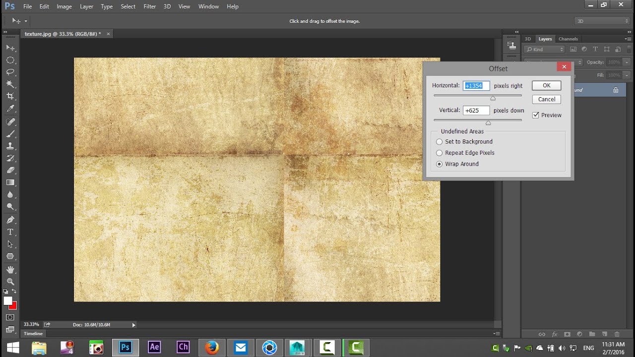
 https://medium.com/geekculture/height-and-normal-maps-in-unity-hdrp-324fefb0d188
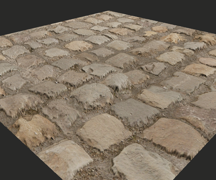
 https://assetstore.unity.com/2d/textures-materials
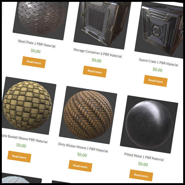
 https://texturefun.com/

 https://www.cgbookcase.com/
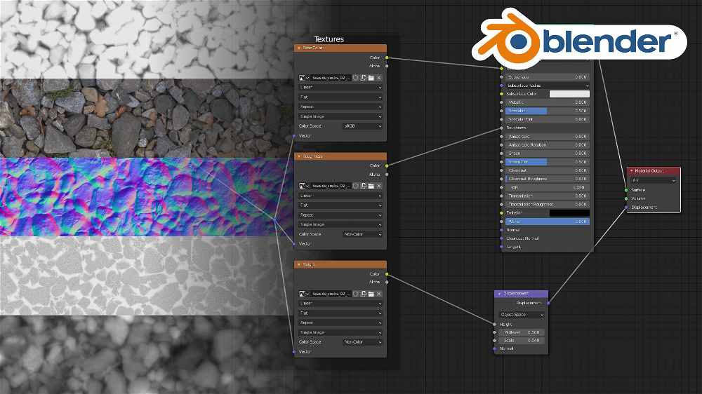
 https://www.sharetextures.com/
Adding Videos (render textures)
In Unity, a Render Texture is a special type of texture that is created and updated at runtime. It allows you to render the output of a video (or camera) to a texture, which can then be used as the input for another camera, a material, or even a GUI element.
In this example, we want to utilize a surface of the 3D model to display the contents of a video file. Therefore, a render texture will assist us in creating this effect. To do this we need to complete the following steps:
- Create a Video Player object – A Video Player can be added to our project by selecting GameObject / Video / Video Player. This will add a new video object on the Hierarchy panel. From the Inspector we have the option to load a video file to the object (the video file has to be already added in our Assets folder; .mp4 file format is strongly suggested).
- Create and assign a Render Texture – A Render Texture is a type of texture that Unity creates and updates at run time. To use a Render Texture you need first to create a new Render Texture asset in the Assets panel. This can be created either by right-clicking in the Assets folder, or by selecting in the main menu: Assets / Create / Render Texture. When the texture is created, we can review its Inspector and set its size to the value that it is needed (i.e. SD/HD, etc). After this is set, go back to the Video Player and set its Target Texture option to the new render texture we have just created.
- Create a Geometry & Material – In this instance we want the video to appear on a geometry – a 3D object that contains a special material that allows it to display the video frames. To complete this task, we can create a new 3D GameObject (i.e. plane) and position it where it is needed. Finally, we have to create a new material as this will be needed to give to the 3D object its final surface look. Here, we need to assign to the Base Map / Albedo settings of the color the Render Texture that we have just created. To do this, drag the Render Texture file from the Assets folder, to the little square that appears on the name Base Map / Albedo inside our new material.
- Create a Video Player object – A Video Player can be added to our project by selecting GameObject / Video / Video Player. This will add a new video object on the Hierarchy panel. From the Inspector we have the option to load a video file to the object (the video file has to be already added in our Assets folder; .mp4 file format is strongly suggested).
-
Generative 3D
Importing 3D Models
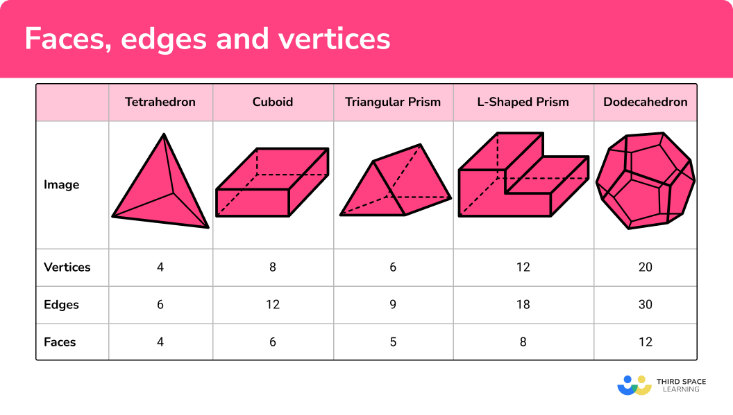
3D models are digital representations of objects or characters that can be used in various applications such as video games, animation, and virtual reality. They are typically composed of a set of polygons, which are used to create the shape of the object, and a set of textures, which are used to control the visual appearance of the object. There are several different file types and properties that are commonly used for 3D models:
- OBJ: The OBJ file format stores the geometry of the model as a set of vertices and faces, and can also store information about materials and textures. OBJ files are widely supported by most 3D modeling software and can be easily imported into many game engines.
- FBX: The FBX file format is a more advanced format for storing 3D models. It supports a wide range of features, including support for animation, lighting, and cameras. FBX files can also store information about materials and textures, and are supported by many 3D modeling software and game engines.
- STL: The STL file format is primarily used for 3D printing and is a standard file format for 3D models. It stores the geometry of the model as a set of triangles, and does not typically include information about materials or textures.
Unity supports a range of 3D models and objects. We can either using Unity’s primitives, or import them from elsewhere. Importing models can be straightforward – drag and drop in the Assets folder suffices. It is strongly suggested to use .FBX or .OBJ file types, or, if you use Blender, you can directly import Blender’s project file in Unity (.blend).
3D models can be created with a range of software (e.g., Blender, Maya, Rhino, Fusion360, etc). We can also find models on the public domain:
Use LumaAI for Generative 3D models
 https://docs.unity3d.com/Manual/3D-formats.html
 https://docs.unity3d.com/560/Documentation/Manual/HOWTO-importObject.html
 https://sketchfab.com/features/free-3d-models

 https://www.turbosquid.com/Search/3D-Models/free
 https://threedscans.com/
 https://www.3dassets.one/#order=latest
Homework (14 April)
Unity Practice
Create a composition in Unity (URP, v6) that integrates the following:
- At least three different 3D models (created in Luma Genie) – each model can be added multiple times if needed into the composition
- Each 3D model needs to have their own custom-made texture (and shader)
- At least two planes (or other primitives or custom 3D models) that make use of video render textures.
- Make use of the given motion scripts to animate selected 3D objects
After you finalize the composition, you need to record it using the Unity Recorder (~30 seconds, FullHD, .mp4 file format). Upload your final video here.
Unity Recorder Instructions
The Unity Recorder is a tool that allows you to record images or videos of your project. Before you can wor with the Unity Recorder, make sure that you install it from Window > Package Manager.
On the Package Manager, make sure that you select Unity Registry on the top left menu (next to the + icon). Then, use the search bar to find the asset, and install it into your project.
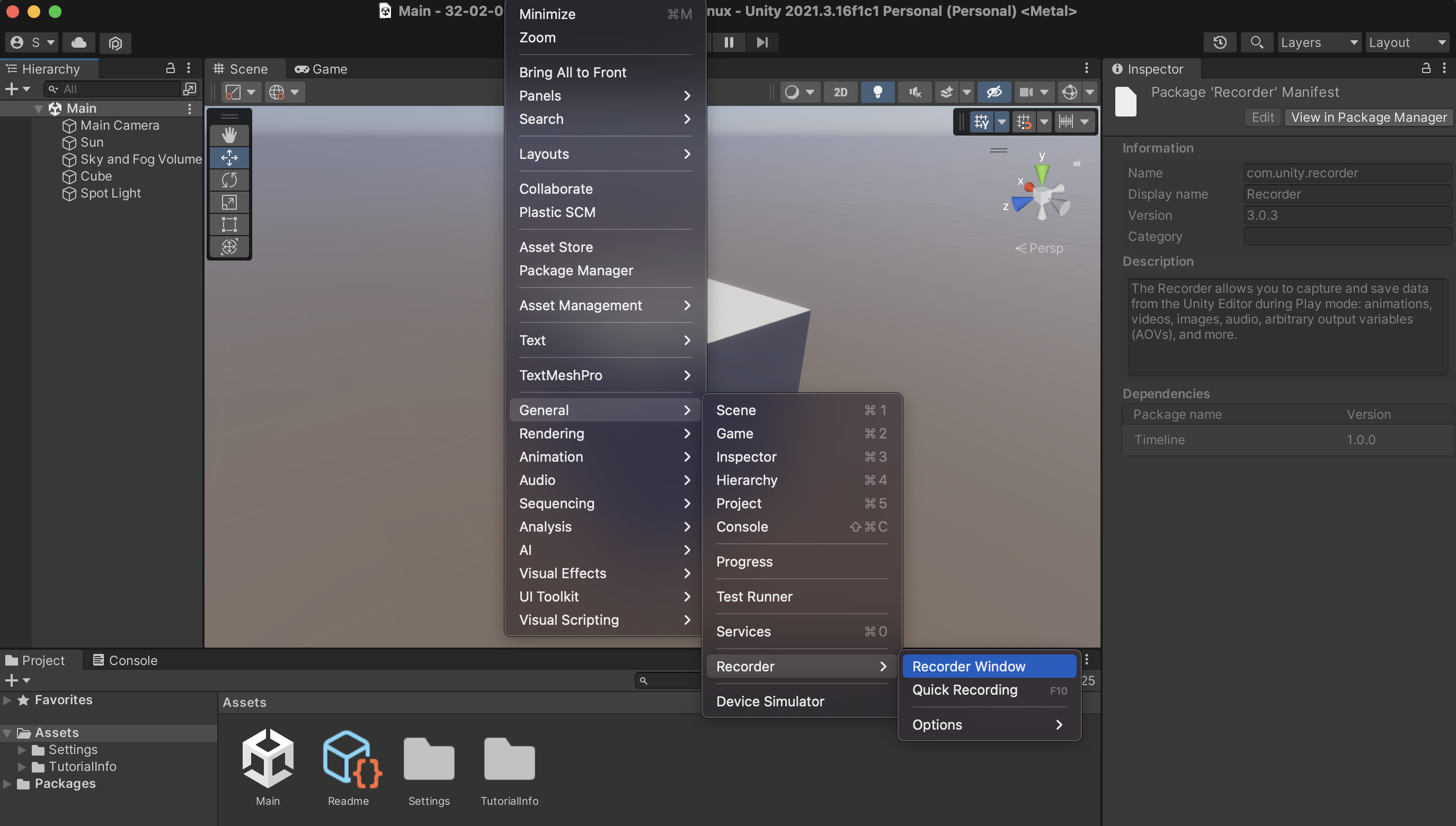
To open the Unity Recorder after you have installed it, go to Window > General > Recorder > Recorder Window. The Recorder window allows you to create a new recorder type (such as Animation Clip, Movie, Image Sequence, etc), and define the settings for your recording. If for example you select Add Recorder > Movie, the window will display settings for the Source needed for the recording (i.e. Game view window), resolution, the format of the recorded video file, frames per second, and so on.
In this example, it is recommended that you use the following settings:
- 30 FPS
- FHD – 1080p
- H.264 MP4, Quality High
By hitting START RECORDING, the game view will execute, and the video file will be recorded. You can stop the recording by exiting the game view, or pressing STOP RECORDING. The file will be saved to the directory that you have assigned it. Its preset directory is within the project folder (inside the folder Recordings).

Further instructions here:
 https://learn.unity.com/tutorial/working-with-unity-recorder#
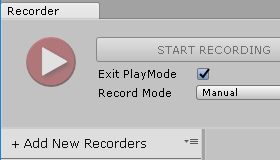
S10. Integration with Unity (interaction, shaders, VFX)
Prefabs
A prefab (pre-fabricated) GameObject is an object entity that can be customized and then instantiated as many times as desired within the rendered space. A prefab can include any combination of components such as meshes, materials, animations, scripts, and other objects. The advantage of using prefabs is that they allow you to easily reuse objects and make global changes to all instances of the prefab by modifying the original asset.
Here is a basic method for creating and using a prefab:
- Create a new GameObject in the scene or select an existing one.
- In the Project window, right-click and select “Create > Prefab”. Drag the GameObject from the Hierarchy window to the newly created Prefab asset in the Project window.
- You can also drag a GameObject from the Hierarchy window to the Project window (Assets). This will directly create a Prefab for the GameObject.
- You can now delete the original GameObject from the Hierarchy view.
- To instantiate the prefab in the scene, simply drag it from the Project window into the Hierarchy window.
- You can modify the properties of individual instances of the prefab without affecting the original asset. If you want to make a change to all instances, simply modify the original prefab (found in Assets).
Note: Prefab variants allow you to create different variations of a prefab while still linking them to the original. This can be achieved through the settings in Overrides.


-
Scripting with C#
Scripting in Unity refers to the process of creating code to control the behavior and functionality of GameObjects in a Unity scene. Unity supports scripting in C#, UnityScript (a variant of JavaScript), and Boo (a language similar to Python).
Scripts in Unity are attached to GameObjects as components and contain code that modifies the GameObject’s behavior and properties in response to events in the game. A script can be used to handle user input, control animations, manage physics, and perform many other tasks.
To use a script in Unity follow this simple flow:
- Create a new script: To create a new script in Unity, you can right-click in the Assets panel and select Create > C# Script or another supported language.
- Attach the script to a GameObject: To attach a script to a GameObject, you can drag the script from the Assets panel onto the GameObject in the Scene or Hierarchy panel. The script will appear as a component in the Inspector panel.
- Steps 1 and 2 can be also done directly from within the Inspector of a GameObject. Click on the GameObject on the Hierarchy panel, and on the Inspector click on Add Component > New Script.
- Write Code: The created script appears both on the Inspector window of the GameObject that we have attached to it, and also on our Assets folder in the Project window. Double clicking either the file from the Project window, or from the GameObject’s Inspector, the script will open on Visual Studio Code, where we can edit and save it.
- Update the Code and Run: After we edit the code and save it, we need to Run the program, during which the code will execute. The GameObject‘s behavior and properties are going to be updated according to the code we have written.
In the following example, we attach a new script to a Prefab. Our objective is to write an instruction that continuously rotates the GameObject around its axis. The code for the rotation of the GameObject around its X,Y,Z axis is as follows:
//Imports
using System.Collections;
using System.Collections.Generic;
using UnityEngine;

//Name of our newly created script (Rotation.cs)
public class Rotation : MonoBehaviour
{
		//Public variables (these appear on the Inspector
    public float rotationSpeedX = 10f;
    public float rotationSpeedY = 10f;
    public float rotationSpeedZ = 10f;

    // Start is called before the first frame update
    void Start()
    {
    }

    // Update is called once per frame
    void Update()
    {
				//Call transform.Rotate a method for controlling GameObject rotation
        transform.Rotate(Vector3.right * Time.deltaTime * rotationSpeedX);
        transform.Rotate(Vector3.up * Time.deltaTime * rotationSpeedY);
        transform.Rotate(Vector3.forward * Time.deltaTime * rotationSpeedZ);
    }
}
In this example, the
rotationSpeedX,rotationSpeedY, androtationSpeedZvariables determine the speed of the rotation along the x, y, and z axis, respectively. Thetransformproperty refers to the transform component of the GameObject, which contains its position, rotation, and scale.The
Rotatemethod rotates the GameObject around the specified axis by the specified angle. In this case, theVector3.rightrepresents the x-axis,Vector3.uprepresents the y-axis, andVector3.forwardrepresents the z-axis. The rotation angle is determined byTime.deltaTime * rotationSpeed, whereTime.deltaTimerepresents the time in seconds since the first frame, androtationSpeedis the speed of the rotation.This script will continuously rotate the GameObject around its x, y, and z axis by the specified rotation speed. You can adjust the
rotationSpeedX,rotationSpeedY, androtationSpeedZvalues to control the speed of the rotation along each axis from the Inspector panel of the GameObject.
Scripts can be attached to Prefabs as well. In the following example, a Prefab has been created that includes multiple cubes nested together. The previous script has been adjusted to generate random rotation speed values for each cube. Therefore, upon the initialization of the code, each cube will be controlled with a different rotational speed. The randomization of the values is done with the use of the
Random.Rangefunction.
using System.Collections;
using System.Collections.Generic;
using UnityEngine;

public class RotationRandom : MonoBehaviour
{
    public float rotationSpeedX = 0f;
    public float rotationSpeedY = 0f;
    public float rotationSpeedZ = 0f;

    // Start is called before the first frame update
    void Start()
    {
        //Generate random values for rotational speed (X,Y,Z);
        rotationSpeedX = Random.Range(-60.0f, 60.0f);
        rotationSpeedY = Random.Range(-60.0f, 60.0f);
        rotationSpeedZ = Random.Range(-60.0f, 60.0f);
    }

    // Update is called once per frame
    void Update()
    {
        transform.Rotate(Vector3.right * Time.deltaTime * rotationSpeedX);
        transform.Rotate(Vector3.up * Time.deltaTime * rotationSpeedY);
        transform.Rotate(Vector3.forward * Time.deltaTime * rotationSpeedZ);
    }
}
The following links provide comprehensive details regarding scripting in Unity.
In the next class, we will focus more comprehensively on coding, and generative art & design.
Iterations (For-Loops)
A
forloop is a control structure in programming that allows you to execute a block of code a specified number of times. It is defined with a starting value, a limit, and an increment value (step), and executes the code within the loop until the limit is reached.In Unity,
forloops can be used to perform repetitive tasks, such as initializing an array, updating elements in a list, or creating multiple instances of a GameObject.Here’s an example of how a
forloop can be used to initialize an array in Unity.using UnityEngine; public class forLoops : MonoBehaviour { // Start is called before the first frame update void Start() { int[] numbers = new int[10]; for (int i = 0; i < 10; i++) { numbers[i] = i; Debug.Log(numbers[i]); } } }In this example, the
forloop starts with the value ofibeing 0, and continues to loop untilireaches 9 (the limit of 10 – 1). Each time the loop iterates,iis incremented by 1 (the increment value). The code inside the loop sets the value of thenumbersarray at the indexitoi(0,1,2,….9).More info on for-loops and Unity:
Code Example: 1D For-Loop
The following example demonstrates a
forloop to instantiate multiple instances of a prefab.using UnityEngine; public class PrefabInstantiator : MonoBehaviour { public GameObject prefab; void Start() { for (int i = 0; i < 10; i++) { Vector3 position = new Vector3(i * 2, 0, 0); Instantiate(prefab, position, Quaternion.identity); } } }Here, the
forloop starts with the value ofibeing 0, and continues the loop untilireaches 9 (the limit of 10 – 1). Each time the loop iterates,iis incremented by 1 (the increment value). The code inside the loop calculates a new position based on the value ofiand uses theInstantiatefunction to create a new instance of theprefabat that position.
Code Example: 2D For-Loop
Nested loops in Unity allow you to loop through multiple dimensions and instantiate prefabs in a grid-like or matrix-like pattern. For example, you could use nested loops to create a grid of prefabs, with each prefab representing a cell in the grid. Here’s an example of how you can use nested loops to instantiate prefabs in a 5×5 grid pattern:
using UnityEngine;

public class PrefabInstantiator : MonoBehaviour
{
    public GameObject prefab;

    void Start()
    {
        for (int i = 0; i < 5; i++)
        {
            for (int j = 0; j < 5; j++)
            {
                Vector3 position = new Vector3(i * 2, 0, j * 2);
                Instantiate(prefab, position, Quaternion.identity);
            }
        }
    }
}
In this example, the outer
forloop starts with the value ofibeing 0, and continues to loop untilireaches 4 (the limit of 5 – 1). The innerforloop starts with the value ofjbeing 0, and continues to loop untiljreaches 4. Each time the inner loop iterates,jis incremented by 1. The code inside the inner loop calculates a new position based on the values ofiandjand uses theInstantiatefunction to create a new instance of theprefabat that position.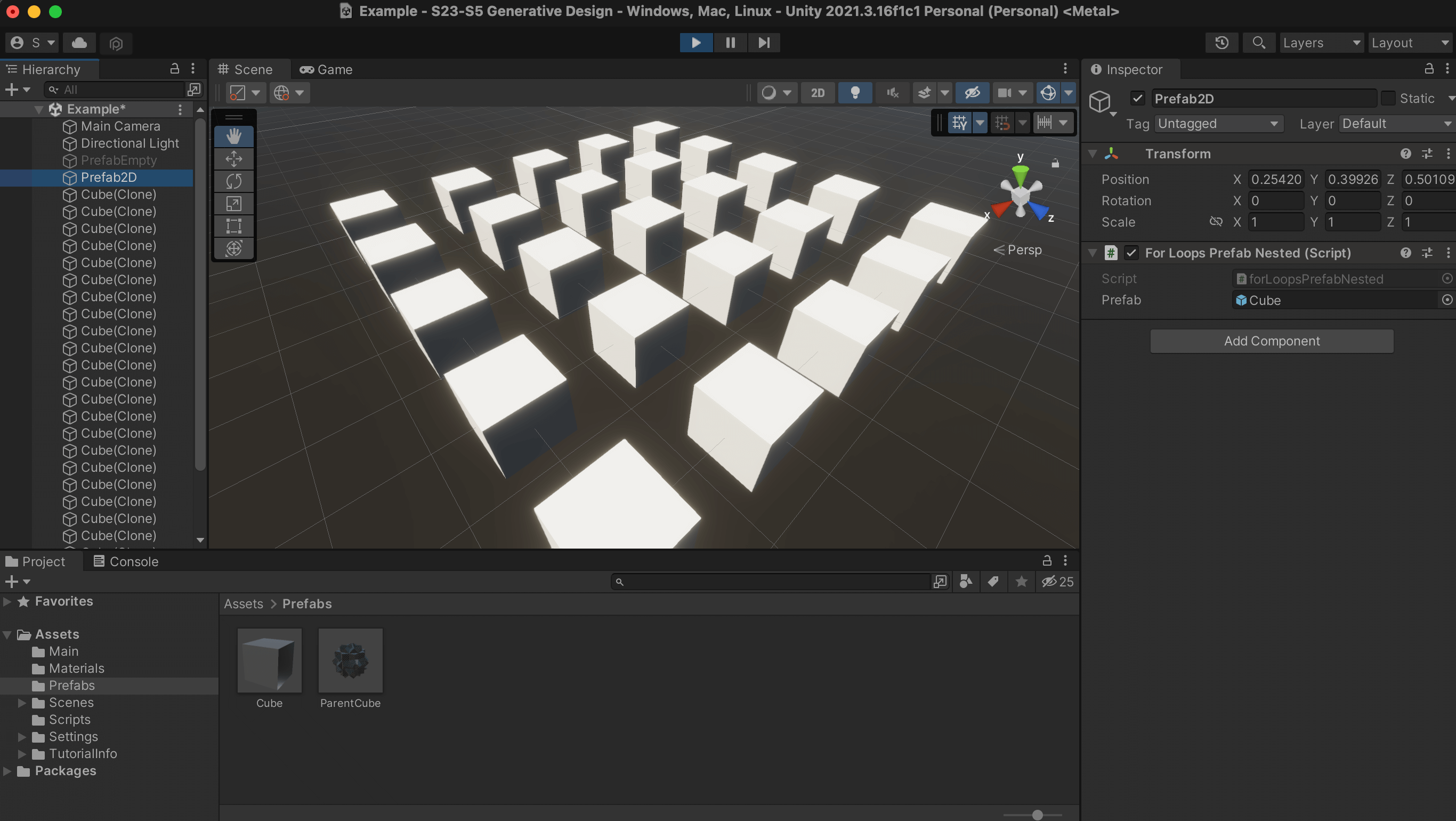
Code Example: 3D For-Loop
The same logic can be used for creating three-dimensional nested loops (see code below).
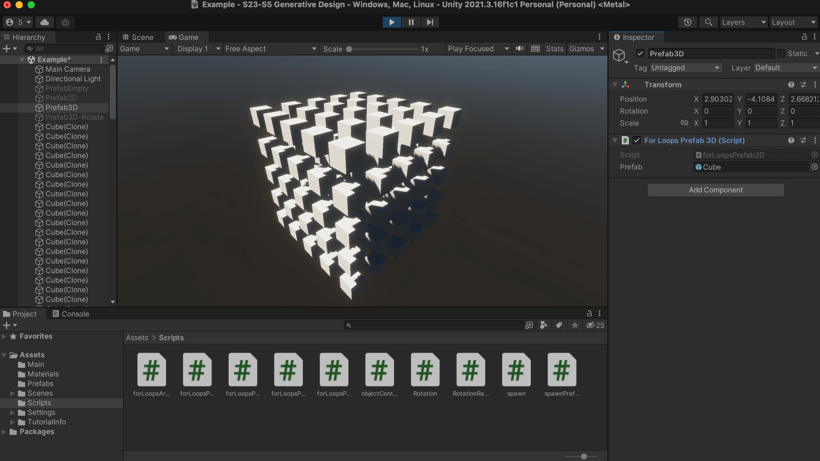
using UnityEngine;

public class forLoopsPrefab3D : MonoBehaviour
{
    public GameObject prefab;

    void Start()
    {
        for (int i = 0; i < 5; i++)
        {
            for (int j = 0; j < 5; j++)
            {
                for (int k = 0; k < 5; k++)
                {
                    Vector3 position = new Vector3(i * 2, k * 2, j * 2);
                    Instantiate(prefab, position, Quaternion.identity);
                }
            }
        }
    }
}
The code creates an instance of a prefab in a 3D grid pattern. It does this by using three nested for-loops that generate a grid of prefab instances.
- The first for-loop
(int i = 0; i < 5; i++)will run 5 times, with the value ofiincrementing from 0 to 4 each time the loop runs.
- The second for-loop
(int j = 0; j < 5; j++)will also run 5 times, with the value ofjincrementing from 0 to 4 each time the loop runs.
- The third for-loop
(int k = 0; k < 5; k++)will also run 5 times, with the value ofkincrementing from 0 to 4 each time the loop runs.
At each iteration of these three loops, a new Vector3 position is calculated by multiplying
i,j, andkby 2(position = new Vector3(i * 2, k * 2, j * 2)). Then, a new instance of the prefab is created at this calculated position using theInstantiate()methodInstantiate(prefab, position, Quaternion.identity).This will result in a grid of 125 instances of the prefab, with each instance being placed 2 units apart from each other.
- The first for-loop
Code Example: Adding Instances as Children
One additional modification that you can do to this example is to put all new instances within the main prefab GameObject, so that it is easier to control all instances at once. This can be accomplished very easily, by simply adding a 4th property within the
Instantiatefunction, so that it reads as below:Instantiate(prefab, position, Quaternion.identity, transform)The
transformkeyword is going to position the newly created prefab within the same GameObject (named Prefab3D-Rotate seen in the following image). Now, if we desire to automate the behavior of this parent (Prefab3D-Rotate), we can add an additional script (rotation.cs) that is going to rotate the parent (and its children, that is, the prefab instances).
Code Example: Rotating the Parent
Finally, if we add a random rotation script within the original prefab (which exists on the Project window), we will get a much more organic behavior.


 https://blog.devgenius.io/unity-3d-c-scripting-cheatsheet-for-beginners-be6030b5a9ed
Shaders
Shaders are programs that run on the GPU and control how a 3D model or a 2D image is drawn. They provide a way to apply effects and transformations to the rendering process, such as changing the color, adding shadows or reflections, and creating animations.
Shaders are written in a custom language called ShaderLab, which is used to describe how the materials in a scene should be rendered. ShaderLab is a high-level shading language that provides an abstract representation of the underlying GPU operations, making it easier for artists and developers to create complex visual effects without having to delve into the low-level details of the GPU.
In Unity, shaders are divided into three broad categories. You use each category for different things, and work with them differently.
- Shaders that are part of the graphics pipeline are the most common type of shader. They perform calculations that determine the color of pixels on the screen. In Unity, you usually work with this type of shader by using Shader objects.
- Compute shaders perform calculations on the GPU, outside of the regular graphics pipeline.
- Ray tracing shaders perform calculations related to ray tracing.

Shader Graph
Shader Graph Intro
Shader Graph is a visual interface for creating shaders in Unity. It allows users to create custom shaders without having to write any code, by using a node-based system that is accessed directly within the Unity Editor. Shader Graph includes a variety of node types, including mathematical operations, texture sampling, color blending, and many more. The nodes can be connected and combined to create complex shaders, from simple surface shaders to complex materials that include reflections, refractions, and other advanced effects.
A few characteristics of Shader Graph are the following:
- Node-Based Interface: The Shader Graph uses a node-based interface, which allows for an intuitive and straightforward creation of shaders without the need for manual shader coding.
- Real-Time Preview: The Shader Graph provides a real-time preview of the shader being created, which allows for immediate feedback on how changes to the graph affect the final result.
- Customization: Shaders created with the Shader Graph can be easily customized to fit the specific requirements of the project.
- Lighting Support: The Shader Graph supports various lighting models, including PBR and Unlit, and includes multiple nodes for configuring and controlling lighting.
- Compatibility with Other Unity Features: The Shader Graph can be used in conjunction with other Unity features, such as Particle Systems, VFX Graph, and the Unity Material Editor.
- Extensibility: The Shader Graph is fully extensible, meaning that users can create custom nodes and use them within their shader graph to perform specialized tasks.
Creating a Shader Graph
The Shader Graph is a standard package included within the HDRP. If your project has been set as HDRP, then you can directly create a new Shader Graph in the Project window by selecting Create > Shader Graph > HDRP > Lit Shader Graph. This will create a new asset in the Project window. By double-clicking the newly created file, the Shader Graph UI opens.
Shader Graph’s interface consists of several key elements, including:
- Graph View: This is the main view of the Shader Graph Editor, where you can create and arrange nodes to build your shader.
- Graph Inspector: The Graph Inspector provides options and properties used to modify the behavior and appearance of the Shader Graph and its nodes.
- The Node Settings are specific to a single node within the graph and control its behavior and properties.
- The Graph Settings provide global options and settings for the entire shader graph. It contains options such as shader quality settings, the graph name, and the active channel mask. Here we can set if we want the shader to be Lit or Unlit, for example.
- Main Preview: The Main Preview window offers a visual representation of how the final shader graph will look when applied to a material.
- Blackboard: This is an area where you can add custom values that can be used by nodes in the Shader Graph. The values set in the blackboard can be accessed by the Inspector of the Shader Graph material
The Master Stack
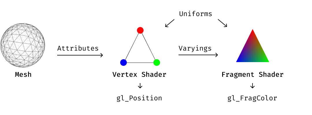
The Shader Graph offers two main blocks: the Vertex and Fragment, also called as Master Stack.
- The Vertex Block is used to modify or manipulate the vertices of a 3D model before they are drawn on the screen. The Vertex Block allows you to make changes to the properties of the vertices and it includes the following basic properties (in HDRP/Lit mode):
- Position – This is the main property of a Vertex Block, which allows you to modify the position of each vertex.
- Normal – This property allows you to modify the normal vector of each vertex, which is used for lighting calculations.
- Tangent – This property allows you to modify the tangent vector of each vertex, which is used for normal mapping or other special effects.
- A Fragment Block is a type of shader block that is used to create and modify the appearance of a material’s pixels. The properties of a Fragment block in the HDRP/Lit mode include:
- Base Color: This property sets the base color of the material, which is the color that is seen before any other effects are applied.
- Normal Tangent Space: This property sets the normal map, which is a texture that defines the surface normals of a material. This can be used to add additional detail and surface roughness to the material.
- Bent Normal: This property sets the bent normal map, which is a texture that can be used to simulate global illumination and subsurface scattering effects.
- Metallic: This property sets the metallic value of the material, which determines how reflective the material is.
- Emission: This property sets the emissive color of the material, which can be used to create materials that emit light.
- Smoothness: This property sets the smoothness value of the material, which determines how smooth or rough the surface is.
- Ambient Occlusion: This property sets the ambient occlusion map, which is a texture that defines the amount of ambient light that should be occluded in the shadows of the material.
- Alpha: This property sets the transparency of the material, which determines how see-through the material is.
- The Vertex Block is used to modify or manipulate the vertices of a 3D model before they are drawn on the screen. The Vertex Block allows you to make changes to the properties of the vertices and it includes the following basic properties (in HDRP/Lit mode):
Vertex Displacement
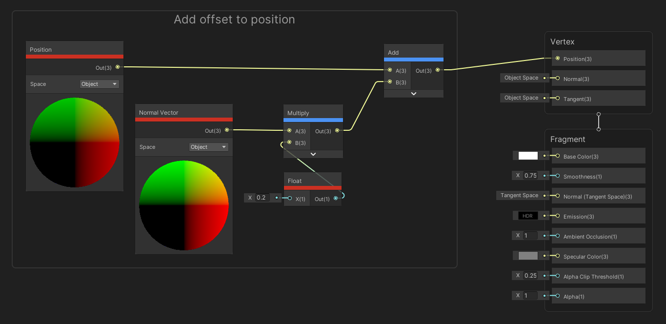
Vertex displacement is a technique where the vertices of an object are moved or displaced along a certain direction in real time based on certain inputs such as noise functions, height maps, or animation curves. The displacement is calculated in the vertex shader and then used to move the vertices before the fragment shader calculates the final pixel colors.
To accomplish the design of a shader, we need to use the nodes and blocks of Shader Graph. To add a new node, mouse-click (or Option click) within the Graph View, select Create Node, and add new nodes according to the requirements of the shader.
The following image shows a simple graph that can be used to access the vertex properties of a model, and reposition the object to a new location within the scene. The shader includes a Position node, a Normal Vector, a Multiply, an Add and a Float node.
- The
Positionnode represents the position of each individual vertex in 3D space. It allows you to control how the mesh deforms, stretches, and twists.
- The
Normal Vectornode is used to represent the normal direction for each vertex of a mesh. The normal vector points away from the surface and is perpendicular to it. It is used to control how light behaves on the surface, which affects the appearance of shading, highlights, and reflections.
- The
Multiplynode multiplies two values together. It is commonly used in combination with other nodes to control the strength of an effect or to create masks.
- The
Addnode adds two values together. It can be used to combine different values and create new ones.
- The
Floatnode allows you to input a floating-point value into the shader. This node can be used to control various properties of the shader such as the amount of a specific effect, the color of a material, the brightness, etc.
To test out the graph, we need to Save Asset (from the top left menu of the Shader Graph window), and use this newly created shader as a material that is added onto a geometry GameObject (or an imported Mesh).
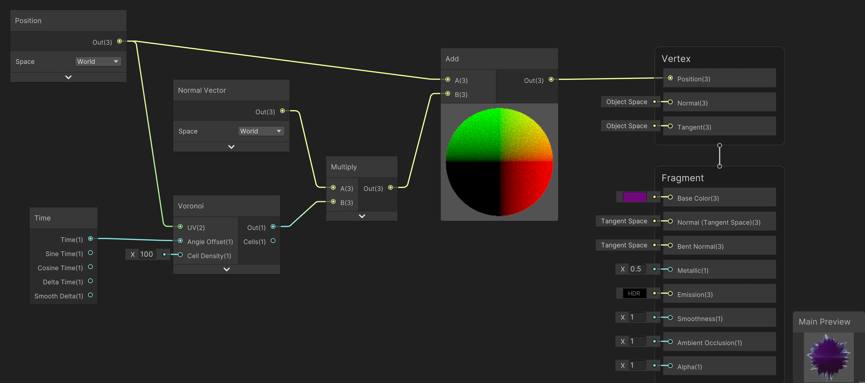
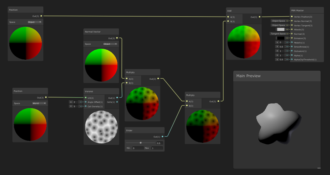
The following image (and tutorial) shows how to create a more advanced vertex displacement shader. The graph contains many nodes as the previous example, but it also includes a Time and Voronoi nodes.
- The
Timenode represents the time in seconds that has passed since the scene was loaded. It can be used to animate materials and create effects over time, such as waves, oscillations, and pulsations.
- The
Voronoinode creates a Voronoi pattern based on a set of input points. It is commonly used to create effects such as noise, patterns, and textures. The Voronoi pattern is generated by dividing the surface into cells based on the distance to the closest input point. Each cell can then be colored differently to create the final effect.
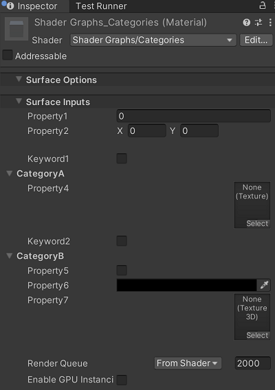
The values of the shaders that we design in Shader Graph can be accessed from the Inspector of the material (the material that was created directly from the shader). In order to achieve this, we need to expose these values on the Blackboard window. Here, you can create new variables, set their types, and assign values to them. Once a variable is created in the Blackboard, it can be used by other nodes in the graph.
For example, you can create a float variable in the Blackboard and use it to control the intensity of a light in the scene. By referencing the variable in the relevant nodes, you can change the value of the light intensity at runtime and have it affect multiple nodes in the graph, all with a single change.
Exposed Properties are variables that are made available to the Inspector and can be adjusted at runtime.
- The
Fragment Shaders
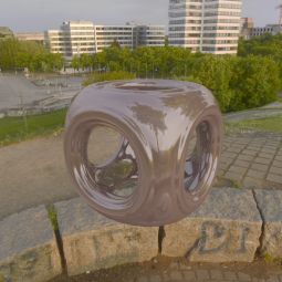
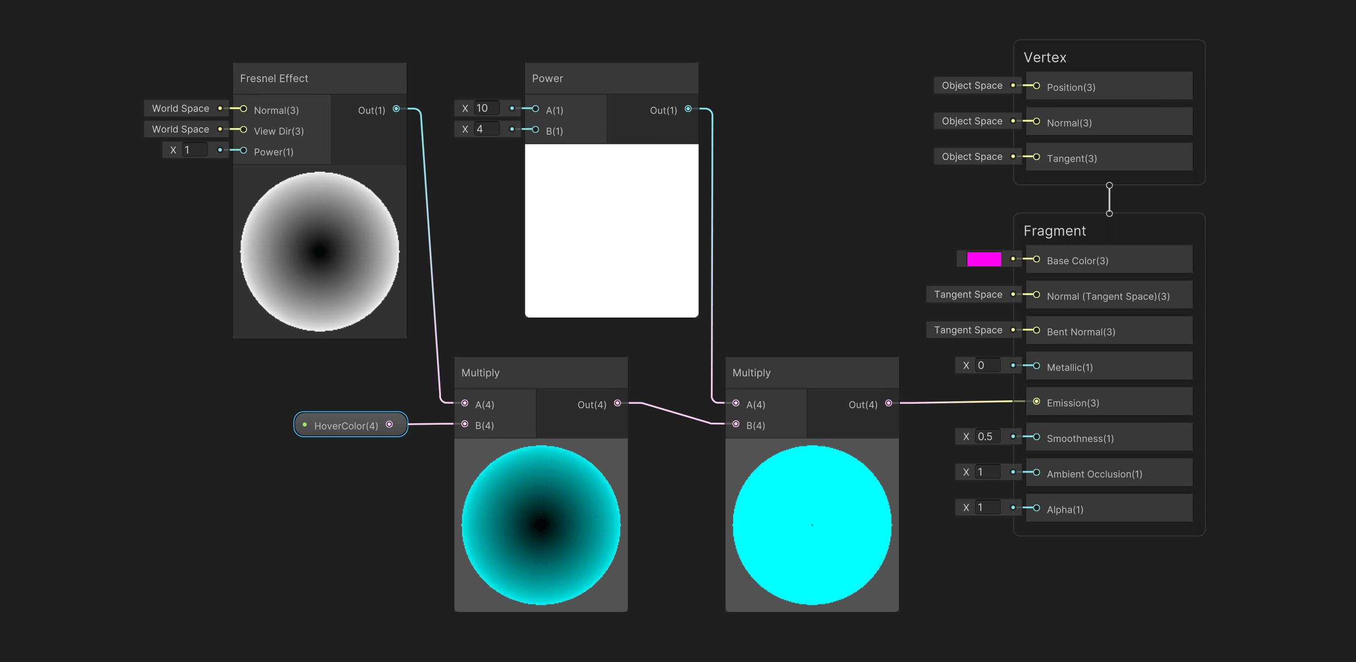
The following example makes use of the Shader Graph to create a glowing ball. Here, we will make use of Fragment Block’s Emission property. The nodes that we are using are the following:
- The
Fresnel Effectis a shader that simulates the way light interacts with the surface of an object. It is the difference in the amount of reflection based on the angle of the light source. In Shader Graph, you can use the Fresnel node which calculates the reflection based on the angle between the surface normal and the camera. This can be used to give the appearance of a glossy or reflective surface.
- The
Powernode allows you to raise a value to a specified power. This is useful for controlling the intensity or distribution of a value across the surface of an object. For example, you can use a Power node to control the strength of a Fresnel effect by raising the value from the Fresnel node to a specified power. This can be used to make the Fresnel effect more or less intense.
In this example, the Fresnel Effect is multiplied by the input color (exposed property, found on the Inspector of the material). Following that, this value is multiplied with the Power node; a higher value here indicates a stronger effect. Finally, the result of the calculation is sent to the Emission property of the Fragment Block.
Extending the previous example, we can incorporate an image to the Base Color of the shader so that we create a more detailed texture. The new nodes used in this example are:
- A
Texture 2D Assetis a 2D image that can be used as a material property in the Shader Graph. It can be used to control the look of the surface of a 3D object by providing additional detail and variation. The Texture 2D Asset node allows you to access a specific texture asset from your project’s Assets folder and pass it to other nodes for use in the shader.
- The
Sample Texture 2Dnode in Shader Graph in Unity is used to sample a texture and get its color information to use as input in a shader. It allows you to use a texture to influence the appearance of your materials. The node can be found in the Texture category of the Node Library in the Shader Graph Editor. TheSample Texture 2Dnode takes in a Texture 2D input and UV input, which is used to determine the sampling position in the texture. The UV input is typically generated by other nodes that create UV coordinates. The UV coordinates are used to map the texture onto the surface of the object being rendered.
- The
Tiling and Offsetproperty defines how a texture is repeated and positioned on an object’s surface. The Tiling property sets the number of times the texture should repeat in both the X and Y directions, and the Offset property allows you to shift the texture’s position in both the X and Y directions.
Vector2is a data type in Shader Graph that represents a 2D vector. It is used to store 2D positions, distances, and sizes. In the context of texturing, it is often used to store the tiling and offset values, allowing you to adjust the position and scale of a texture.
The example below allows us to import an image and use it as a texture for the Base Color. The UV of the sample texture is adjusted by the Tiling and Offset node. In the Offset input, we receive a Vector2 value that consists of a continuously changed number for the X (Y remains at 0). In this instance, we utilize the Time node to push new numerical values to the system, which is then used for a continuous offsetting of the image on the texture plane.
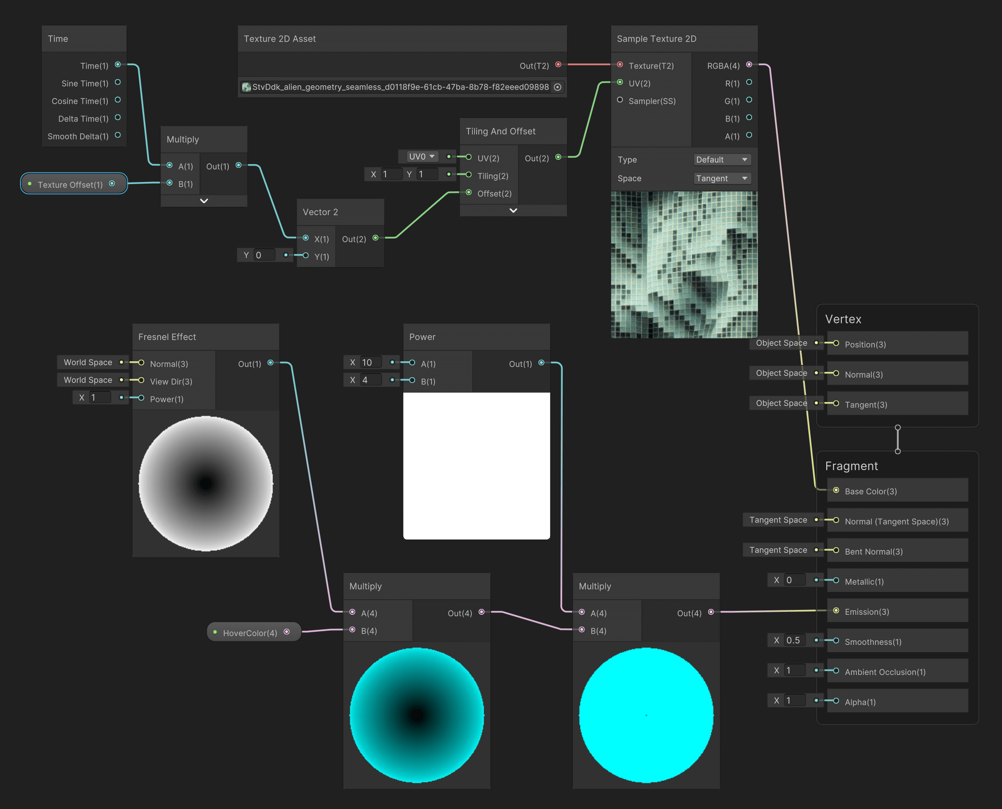
- The
Resources


 https://blog.logrocket.com/getting-started-unity-shader-graph-nodes/


 https://www.amazon.com/Unity-2021-Shaders-Effects-Cookbook-ebook/dp/B0964CKCX6
VFX
Inspiration
- Case Study 1: Refik Anadol, Machine Hallucinations (2021)
MACHINE HALLUCINATIONS is an ongoing exploration of data aesthetics based on collective visual memories of space, nature, and urban environments. Since the inception of the project during his 2016 Google AMI Residency, Anadol has been utilizing machine intelligence as a collaborator to human consciousness, specifically DCGAN, PGAN, and StyleGAN algorithms trained on these vast datasets to reveal unrecognized layers of our external realities.
Anadol and his team collect data from digital archives and publicly available resources, then process the millions of photographic memories with machine learning classification models. The sorted image datasets are then clustered into thematic categories to better understand the semantic context of the data universe. This expanding data universe not only represents the interpolation of data as synthesis but also becomes a latent cosmos in which hallucinative potential is the main channel of artistic creativity. As a thoroughly curated multi-channel experience, MACHINE HALLUCINATIONS offers a new form of sensational autonomy via cybernetic serendipity.
- Case Study 2: Ouchhh, AI Data Monolith (2019)
Ouchhh created a cognitive performance by using real-time brain waves at the Deep Space with a South Korean/German trio. At a concert which we visualized the changes in brain wave activities in real-time, we transformed the Delta, Theta, Alpha, Beta and Gamma brain waves into a real-time concert experience that is wrapped around by generating the data about emotion, focus & attention, some auditory and neural mechanisms with electroencephalogram (EEG).
- Case Study 1: Refik Anadol, Machine Hallucinations (2021)
Introduction to the VFX Graph
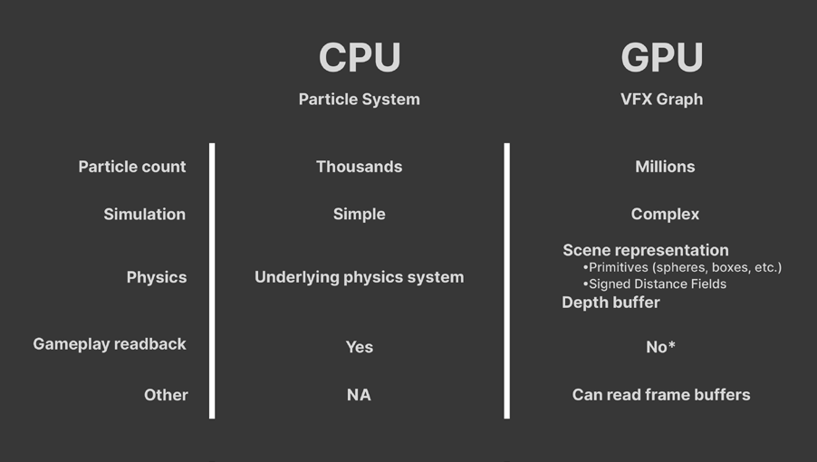
The VFX Graph in Unity is a tool that allows developers and artists to create complex visual effects in real time. It is a node-based system that uses a series of connected nodes to create particle systems and other types of visual effects.
The VFX Graph allows users to create effects with a high level of detail, including dynamic lighting, physics-based motion, and custom shaders. It also includes a range of pre-built templates and effects that can be easily modified and customized to suit individual needs.
Some key features of the VFX Graph include support for GPU instancing, which allows for the efficient rendering of large numbers of objects, and the ability to create custom nodes and effects using C# code. It also includes support for the HDRP (High Definition Render Pipeline) and URP (Universal Render Pipeline), which are Unity’s rendering pipelines designed to support high-quality graphics and real-time rendering.
Overall, the VFX Graph is a powerful tool for creating high-quality visual effects in Unity, and its node-based approach makes it accessible to developers and artists of all levels of experience.
Installations
The VFX Graph works with the High Definition Render Pipeline (HDRP) and it also supports materials and shaders (also compatible with the Shader Graph). VFX Graph operates on the GPU, which allows it to have a much more efficient performance in contrast to other particle systems that are rendered on the CPU.
Package Manager & Settings
VFX Graph comes together with the installation of an HDRP project in Unity (2021). If a project is in URP, the VFX Graph can be installed via the Package Manager.
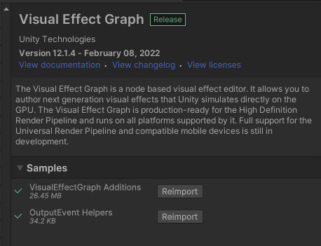
Additional sample content can be found in the package Visual Effect Graph Additions, under Samples in the Package Manager (ensure that the Packages scope is set to Unity Registry).
After installation, the additions can be found under Assets/Samples/VisualEffectGraph.
 💡Another configuration that may be useful at times is activating the Experimental Features of the VFX Graph. You can enable these features via Preferences > Visual Effects > Experimental Operators/Blocks, as shown below.
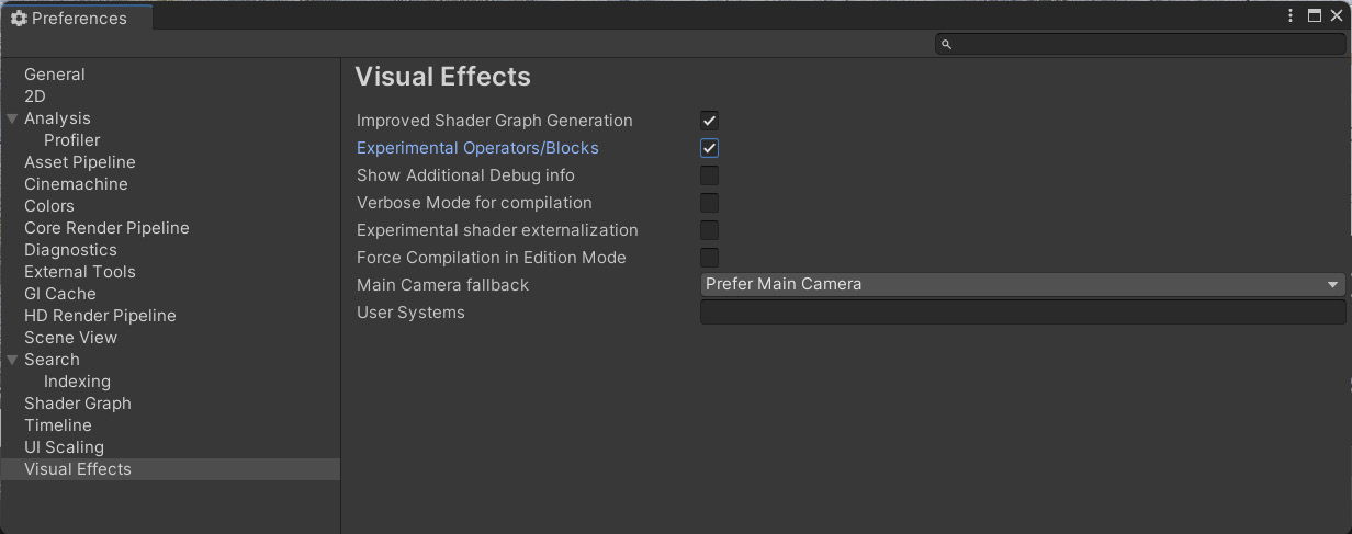
VFX Asset & GameObject
A VFX Graph is a file that can be created and stored in our Assets directory and can be accessed and used as any other asset. There are two main ways to add a VFX Graph to our scene:
- Using our Assets window Create menu, we can select the option Visual Effects > Visual Effect Graph. This will create a new asset that can be dragged into our Scene window.
- Using the Hierarchy’s window Create menu, we can select the option Visual Effects > Visual Effect. Following that, we need to set in the Inspector window a new graph in the option Asset Template. This will create a new VFX Graph that will be added to the Assets folder as well.
When the VFX GameObject has been set up, we can open the graph either by clicking the asset file or selecting in the Inspector the Edit button under the Asset Template.
VFX Graph Window
The VFX Graph Window contains the following elements:
- Toolbar: Provides access to Global Settings, as well as to toggle several panels (sub-windows)
- Node workspace: This is where we compose and edit the VFX Graph.
- Blackboard: Manages exposed properties and global variables that are reusable throughout the graph.
- VFX Control panel: Modifies the playback of the attached GameObject.
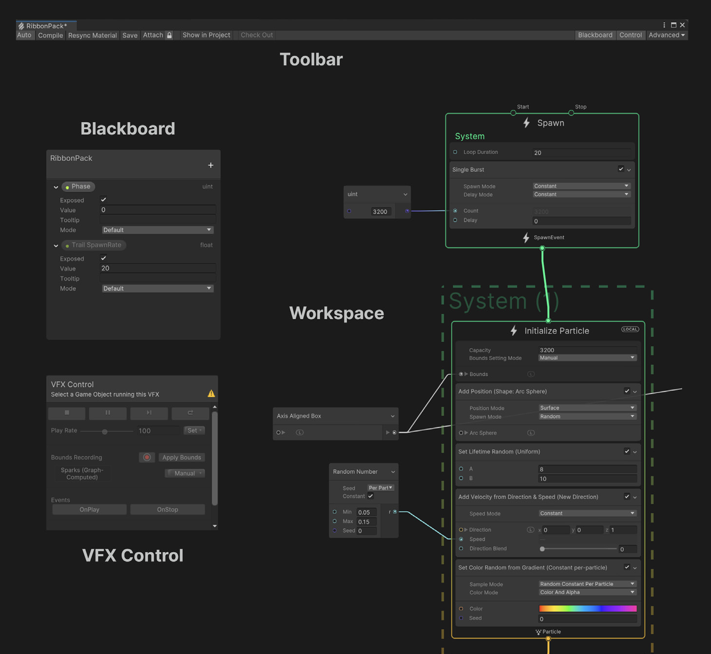
The VFX Graph uses an interface similar to other node-based tools, such as the Shader Graph. To develop a particle system, we need to make use of the nodes that exist within this window and develop our own network of relationships.
A user may press the spacebar or right-click to create a new graph element. With the mouse over the empty workspace, we can select Create Node to create a graph’s Context, Operator, or Property. If for example we select Create Node > System > Empty Particle System, a new system will appear in our window (same as the empty example that Unity creates for us every time we create a new VFX graph).
It is often necessary to use the Inspector window, as it reveals various properties important for the nodes. Make sure to keep it open and visible when you are working with the VFX Graph.
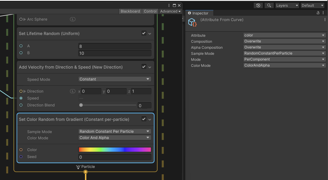
System, Contexts, Blocks
A standard VFX Graph consists of a vertical stack called System. A System defines standalone portions of the graph and encompasses several Contexts. Each System is denoted by the dotted line that frames the Contexts.
For each graph we have the following elements: Spawn, Initialize, Update, and Output. Inside every Context, we find individual Blocks with independent Attributes (for size color, velocity, etc.) for its particles and meshes.
The flow between the Contexts determines how particles spawn and simulate, with the processing of the data happening from top to bottom (vertical logic). Each Context defines one stage of computation:
- Spawn: Determines how many particles you should create and when to
spawn them (e.g., in one burst, looping, with a delay, etc.)
- Initialize: Determines the starting Attributes for the particles, as well as
the Capacity (maximum particle count) and Bounds (volume where the
effect renders)
- Update: Changes the particle properties of each frame; here you can apply
Forces, add animation, create Collisions, or set up some interaction, such
as with Signed Distance Fields (SDF)
- Output: Renders the particles and determines their final look (color, texture,
orientation); each System can have multiple outputs for maximum flexibility.
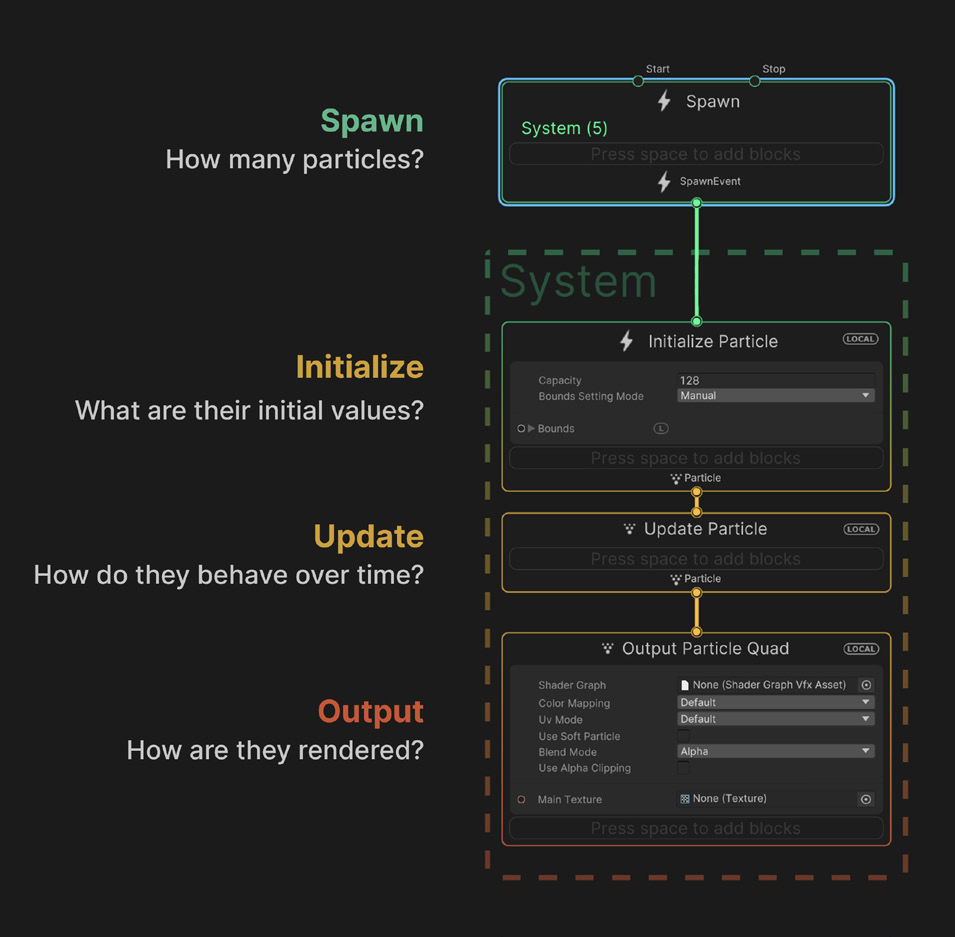
Blocks are nodes that define the behavior of a Context. You can create and reorder Blocks within a Context and, when Unity plays a visual effect, Blocks execute from top to bottom. You can use Blocks for many purposes, from simple value storage (for example, a random Color) to high-level complex operations such as Noise Turbulence, Forces, or Collisions.
 💡When the mouse pointer is on the Context element, you may press Space (on your keyboard) to have the blocks menu appear. The menu will show all available blocks that you can use within this context.
- Spawn: Determines how many particles you should create and when to
VFX Example 1
This example demonstrates how to create a basic particle system in which its motion is affected by turbulence and vector force fields.
Spawn & Initialize
The first step we need to take is to initialize the Rate of the Spawn System, in this case to a number of 1000. This value refers to the constant spawn rate that the particle system is going to use. Set the Capacity of the Initialize context to a similar value.
Initially, the Spawn Rate and the Initialize Capacity may seem similar (if not the same), but they are not. Consider that their difference is the following:
- Spawn Rate: How many particles do we spawn (generate); e.g. Constant Spawn will constantly create the set amount of particles.
- Capacity: Refers to the number of spawned particles that we can hold before they die so that we can spawn them again.
💡Use the Spawn Rate and the Initialize Capacity carefully. Very large numbers will slow down your application and/or crash the computer. Start with reasonable values (for example, 100 or 1000), and adjust gradually.[Block] Set Velocity Random: This block randomizes the velocity of the particles for the X, Y, and Z axes. The values A and B refer to the minimum and maximum values within which the system will generate a random value and assign it to each particle. In our example then, all 1000 particles will instantly get a random velocity value (that is why the particles that appear in the Scene view all have different motion speeds).
[Block] Set Lifetime Random: This block randomizes a float value (within a minimum and maximum range), and assigns the result to the lifetime of each particle. In this example, each particle will have a life span between 2 to 30 frames.
Output
In the VFX Graph, we have multiple options for an Output, that is, the settings we provide for the look and final properties of the particle system. In this example, we are using an Output Particle Quad. This Output context includes options for adding a shader with Shader Graph, Texture, UVs, and Blend Mode, which allow us to set the basic appearance of our particles.
[Block] Orient Face Camera Plane: The Orient Block makes particles orient themselves to face a certain way. With the Face Camera Plane, the particles orient to face forward towards the camera plane. This mode works for most use cases, however, the facing illusion can break sometimes at the edges of the screen (more info here).
[Block] Set Size over Life: This block allows us to control the size of the particle from birth to death. If, for example, we can set the size with a value of 1 at position 0 (birth) to a value of 0.1 at position 1 (death). Thus, the particle will start from its maximum size, and until it does it will shrink to 1/10th of its original size.
[Block] Set Color over Life: With this block, we can control the color of the particle from its birth till it dies. The block allows us to create gradients of color, define the color that we want the particle to have when it first appears on the system, and gradually move from one color value to the other as it reaches its death (in this instance from pink, to light blue, and then to transparent).
Update
Till now, in this example, the particles move in a linear way, from the center outwards till they fade out. In the Update context, we can add blocks to set more sophisticated functions to the particle system. For example, we can add various physics simulations to alter the way that the particle system behaves.
[Block] Turbulence: The Turbulence block generates a noise field which it applies to the particle’s velocity. This Block is useful for adding natural-looking movement to particles. For more information on the types of noise, see the Value Curl, Perlin Curl, and Cellular Curl noise Operators.
[Block] Vector Force Field: The Vector Field Force block uses vector fields to apply a force to the particles. This Block is useful for adding specific forces created in advance and stored in vector field assets.
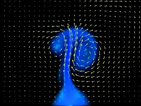
Further development practices:
- Adjust the number of particles (with caution! start from low values, like 500)
- Add a new block to the Initialize context.
- Change the turbulence and vector force field settings.
- Create and assign a custom color gradient.
- Change the particle texture to a custom image (consider a low to mid size .PNG with transparency).
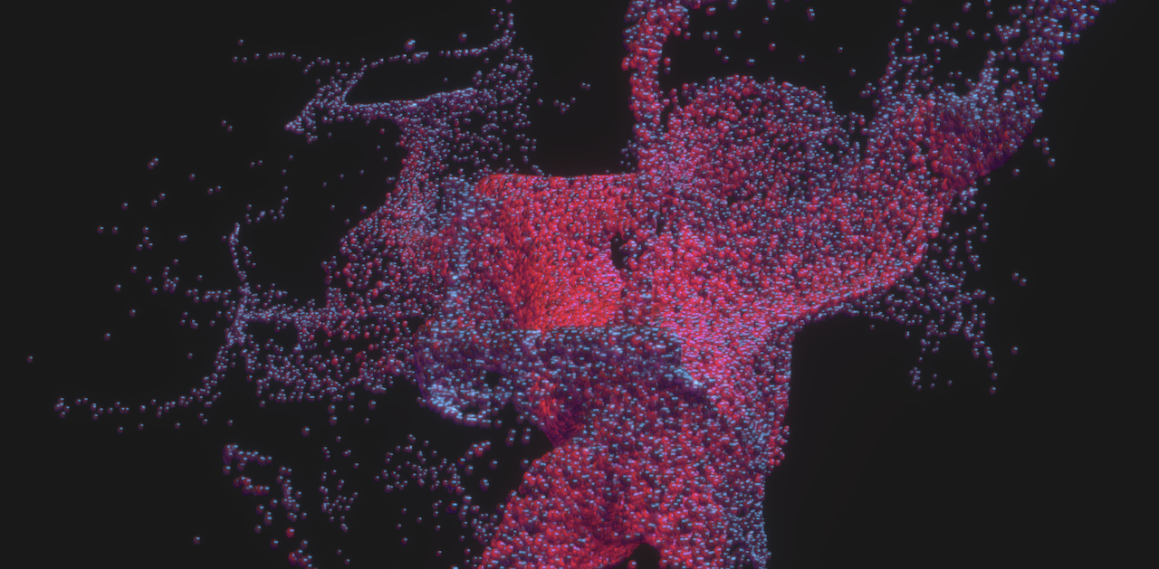
Example result
Properties & Operators
Properties
Properties are editable fields that you can connect to graph elements using Property workflow. They can be found on graph elements such as Contexts, Blocks, and Operators. Properties in the VFX Graph can be of any type, including the following:
- Boolean
- Integer
- Float
- Vectors
- Textures
- Animation Curves
- Gradient
Properties that are made of multiple components (such as Vectors, or Colors) can display every component individually in order to connect these to other properties of compatible type. Use the arrow next to the property to unfold the components.
Operators
Just as Systems form much of the graph’s vertical logic, Operators make up the “horizontal logic” of its property workflow. They can help you pass the custom expressions or values into your Blocks.
Operators flow left to right, akin to Shader Graph nodes. You can use them for handling values or performing a range of calculations. Use the Create Node menu (right-click or press the spacebar) to create Operator Nodes. These Operators from the Bonfire sample, for instance, compute a random wind direction.
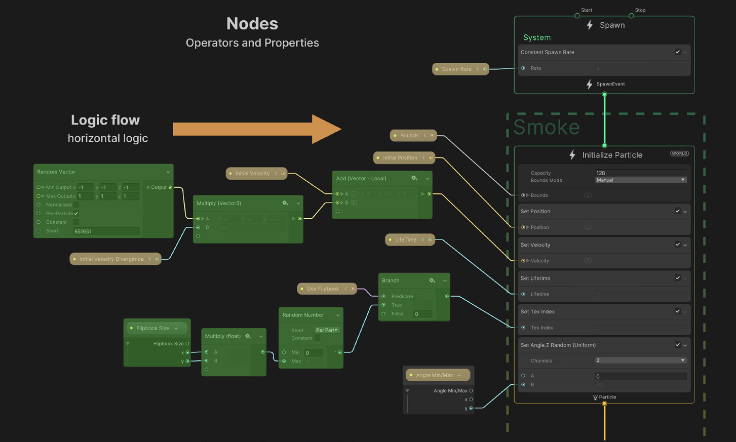
Uniform Operators are Nodes that you can use with a single input of a variable type. For example, you can use absolute values for a float, a Vector3 or an Integer. The output type of any Uniform Operator is always the same as its input type. Connecting a new input with a different type will change automatically the output type of the operator.

In addition to the Uniform Operators, some operators with many inputs can handle multiple inputs of variable types. These Nodes are called Unified Operators; e.g., the Lerp Operator can interpolate between two Vectors uniformly based on a float or every component using a Vector of the same length.

Blackboard & Exposed Properties
The Blackboard is a utility panel that manages Global properties, which can
appear multiple times throughout the graph as Property Nodes. Properties in the Blackboard are either:- Exposed: The green dot to the left of any Exposed Property indicates that
you can see and edit it outside of the graph. Access an Exposed Property
in the Inspector via script using the Exposed Property class.
- Constant: A Blackboard property without a green dot is a Constant. It is
reusable within the graph but does not appear in the Inspector.
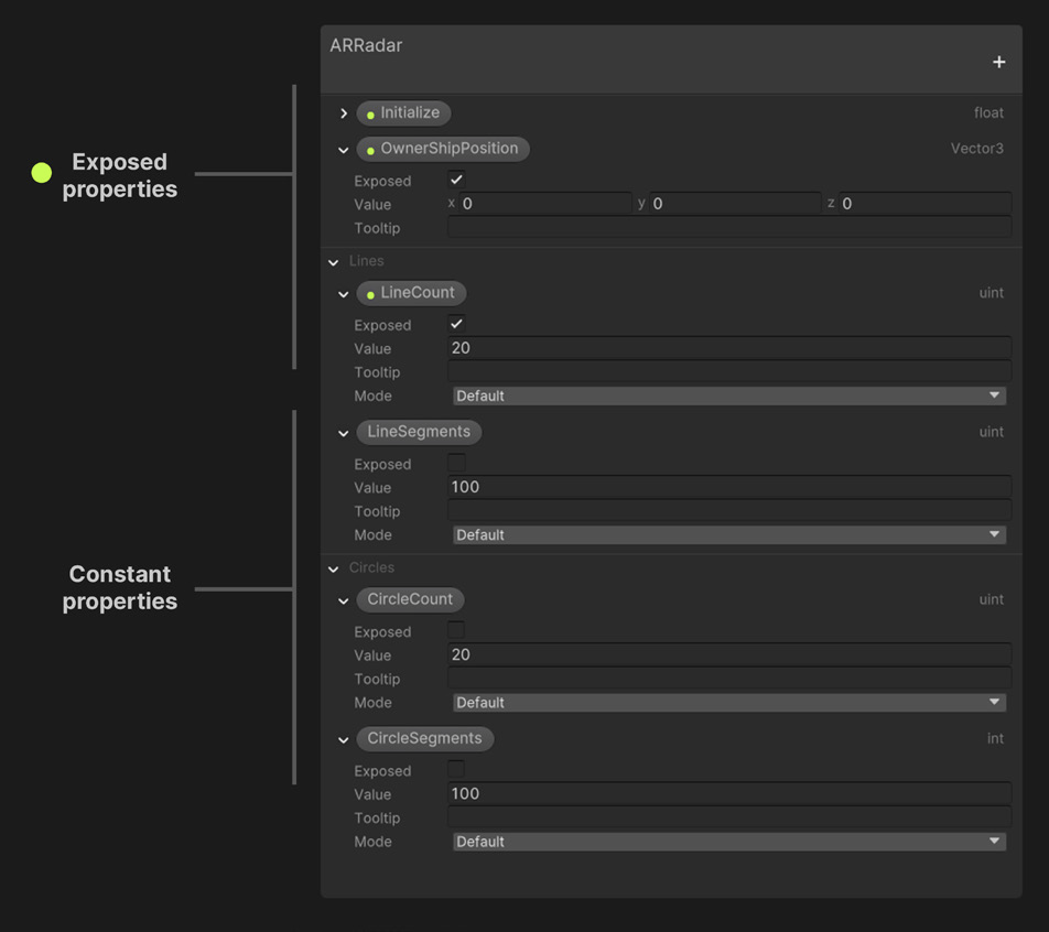
To create a Property Node:
- Drag the Node from the Blackboard Panel into the Workspace.
- To convert a Property Node to an Inline Node of the same type, right-click the property Node and select Convert to Inline.
- When you delete a property from the Blackboard, Unity also deletes its property Node instances from the graph.

- Exposed: The green dot to the left of any Exposed Property indicates that
VFX Example 2
In this example, we will see how to use properties, operators, and the blackboard.
Spawn & Initialize
First, the Spawn Context is set to a Constant Rate of 10000.
The Initialize Particle has a Capacity of 10000. The Set Lifetime Random is set to 2 and 10.
For the Set Position, we use a Shape: Arc Sphere, with Position Mode to Surface, and Spawn Mode to Random.
Operators
For the Set Color, we use a set of operators that allow for two behaviors: the first allows us to select a texture, and from this texture, we extract randomly pixel values that control the color of the particles, and the second one creates an autonomous colorization using the Hue rotation.
The Coloring network uses the following nodes:
- Texture2D: Exposed property that appears on the Blackboard, and we can access it from the Inspector window.
- Use Colormap: Exposed property that appears on the Blackboard, and we can access it from the Inspector window.
- Periodic Total Time: Returns a recurring lapse of time every N seconds, with given range.
- Sample Texture2D: Samples a texture at given position and returns the corresponding value.
- HSV to RGB: Converts a HSV vector to RGB value.
- Branch: Selects one branch or another based on a boolean condition.
Here, the main idea is that based on the conditions set by Use Colormap, which is a boolean that appears on the Inspector, we can set the color of the particle system either based on an image/texture, or using an automatic rotation (through HSV to RGB).
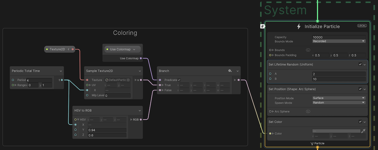
Update & Output
The Update context uses a Turbulence block (same as Example 1). Regarding the Output, we have made the following adjustments:
- Set Size over Life: Here, the size of the particle starts from 0, goes to 0.5 mid life, and goes back to 0 when the life of the particle is over.
- Multiple Color over Life: This block is used to control the color fade of the particle when it reaches its death. Since here we start to multiply the color values with white, all original values that we assigned previously will stay intact. However, as we gradually multiply with darker to black values, the original pixel values will be reduce accordingly (multiply a pixel value with 0, will result to 0).
- Multiple Size: In a similar way we multiply the size of all particles with a variable. According to the value of the block, all particles will scale up/down uniformly.
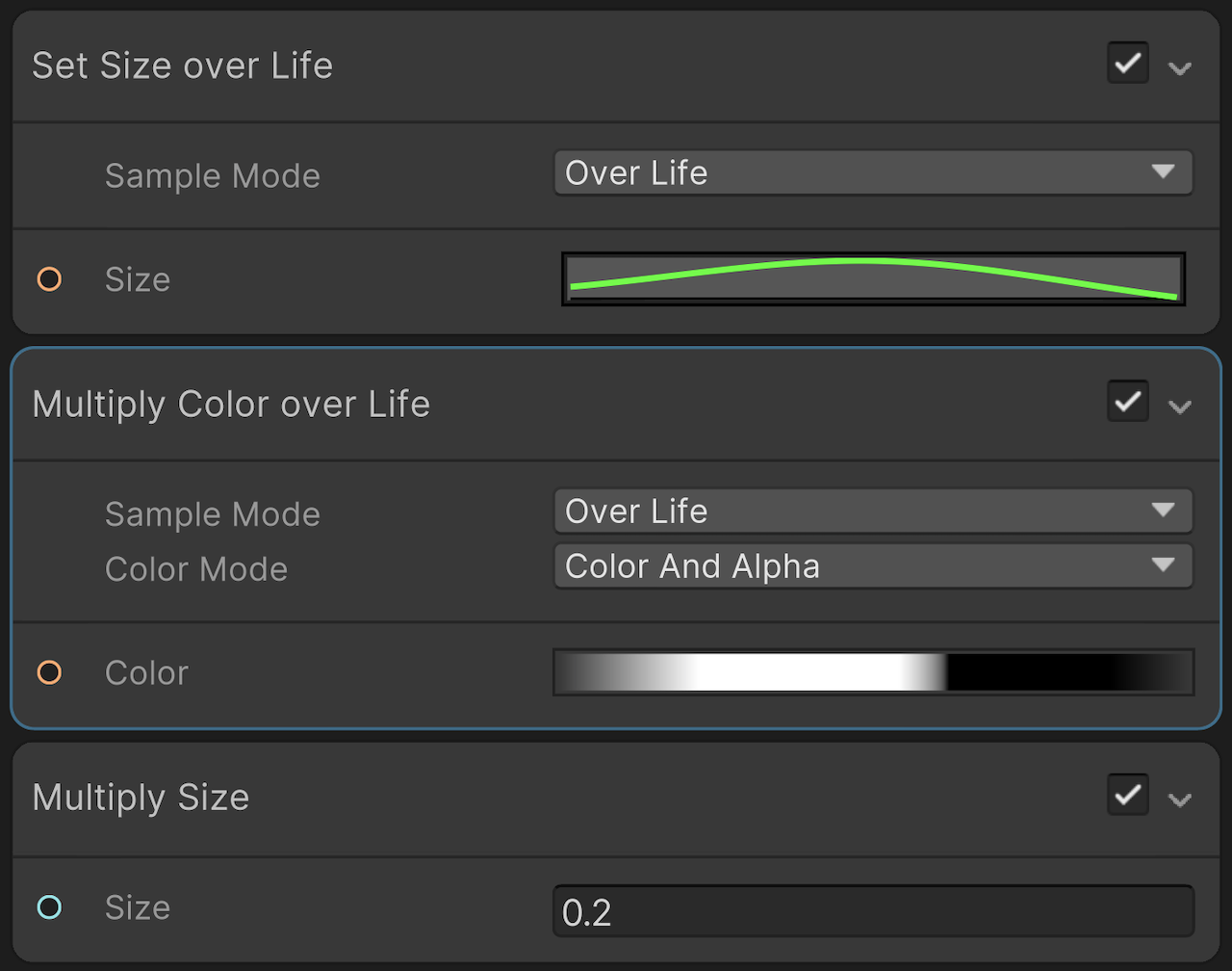
The result of this process appears below. You may see that from the Inspector we can select a new texture, from which the new particles will extract the color pixel values. Also, if we select the exposed property Use Colormap to 1, the particle system uses a continuous rotation of color values.
References
https://github.com/Unity-Technologies/VisualEffectGraph-Samples
Artists working with the VFX Graph
- Keijiro Takahashi
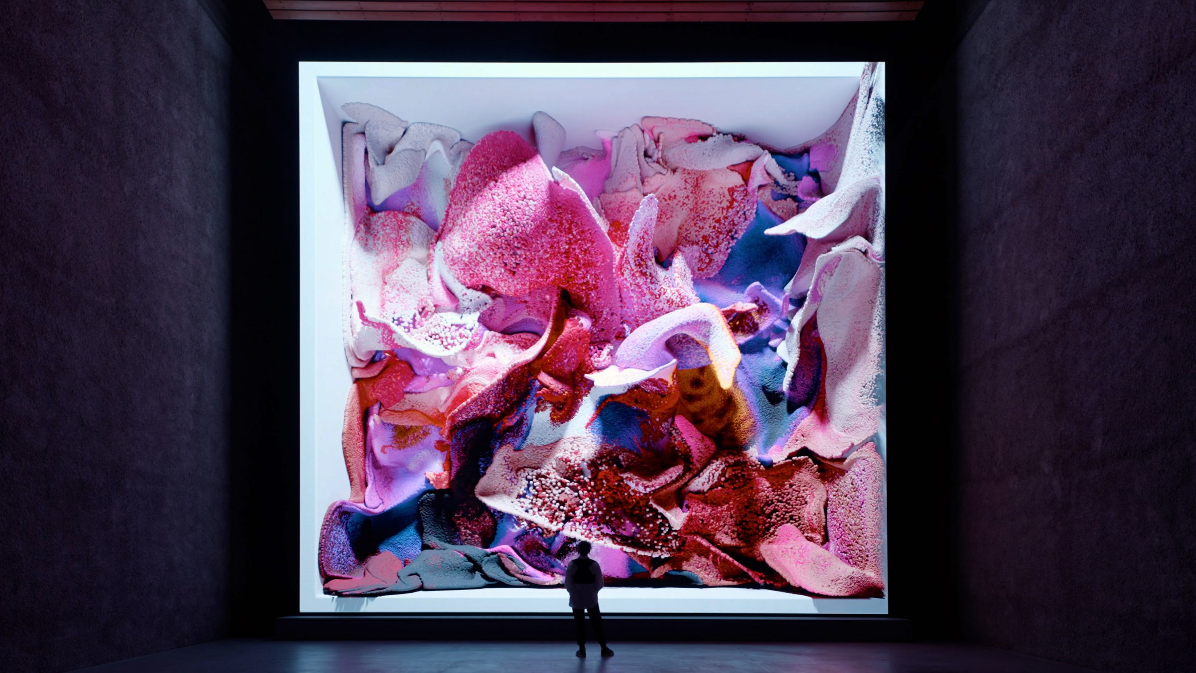
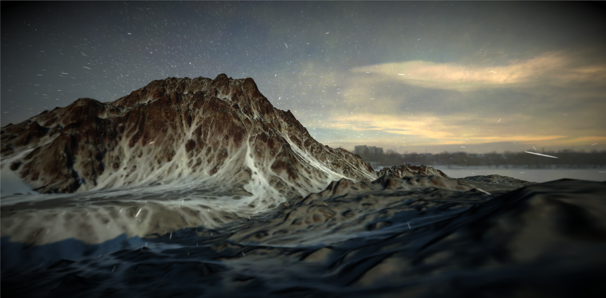
 https://www.youtube.com/watch?v=SUZzJcBIK80&t=1s


 https://benjaminbardou.com/
Proposal for Assignment 3 (Deadline Wednesday 16 April, 1pm)
Complete this form with the details of your project proposal
Homework (21 April)
First Draft of Assignment 3 – Template, Structure, Assets (we will review in class via 1:1 meetings)
S11. Assignment 3: Drafts & Resources


Resources
- VFX Graph Templates
- Materials for ChatGPT
- DeepSeek & Unityhttps://github.com/UnityGameStudio/DeepSeek-Unity
- OpenAI & Unityhttps://github.com/RageAgainstThePixel/com.openai.unity
AI Work Examples
- Meandering River (Onformative)
- Visions of Desctruction (Var&Mar)
Course Readings / References
- Crawford, K. (2021). Atlas of AI: Power, Politics, and the Planetary Costs of Artificial Intelligence. Yale University Press.
- Kissinger, H. A., Schmidt, E., & Huttenlocher, D. (2021). The Age of AI: And Our Human Future. Little, Brown and Company.
- Sautoy, M. D. (2019). The Creativity Code: Art and Innovation in the Age of AI. Harvard University Press.
- Vear, C. & Poltronieri, F.(2026). The Language of Creative AI: Practices, Aesthetics and Structures. Springer.
- Miller, A. I. (2019). The Artist in the Machine: The World of AI-Powered Creativity. The MIT Press.
- Manovich, L., & Arielli, E. (2024). Artificial Aesthetics: Generative AI, Art and Visual Media.
- Macfadyen, L. (2026). Designing AI Interfaces: Design Principles for Creative and Autonomous AI. O’Reilly Publishing.
- Hutson H., Lively, J., Robertson, R., Cotroneo, R. & Lang M. (2024). Creative Convergence: The AI Renaissance in Art and Design. Springer.
- Lee, K.F., & Qiufan, C. (2021). AI 2041: Ten Visions for Our Future. Currency.